Hi,
sorry for the long time for an answer, but I haven't had good days...
This is the code with which happen what I described days ago.
#include <Adafruit_GrayOLED.h>
#include <gfxfont.h>
#include <Adafruit_GFX.h>
#include <Adafruit_SPITFT.h>
#include <Adafruit_SPITFT_Macros.h>

// mapping suggestion for Arduino MEGA
// BUSY -> 7, RST -> 9, DC -> 8, CS-> 53, CLK -> 52, DIN -> 51

// include library, include base class, make path known
#include <GxEPD.h>

// select the display class to use, only one
#include <GxGDEP015OC1/GxGDEP015OC1.h>    // 1.54" b/w

#include <GxIO/GxIO_SPI/GxIO_SPI.h>
#include <GxIO/GxIO.h>

// FreeFonts from Adafruit_GFX
#include <Fonts/FreeMonoBold9pt7b.h>
#include <Fonts/FreeSansOblique9pt7b.h>
#include "Image.c"

#include GxEPD_BitmapExamples

#if defined(ARDUINO_AVR_MEGA2560)

// for SPI pin definitions see e.g.:
// C:\Users\xxx\AppData\Local\Arduino15\packages\arduino\hardware\avr\1.6.21\variants\mega\pins_arduino.h

// select one, depending on your CS connection
GxIO_Class io(SPI, /*CS=*/ SS, /*DC=*/ 8, /*RST=*/ 9); // arbitrary selection of 8, 9 selected for default of GxEPD_Class
//GxIO_Class io(SPI, /*CS=*/ 10, /*DC=*/ 8, /*RST=*/ 9); // arbitrary selection of 8, 9, CS on 10 (for CS same as on UNO, for SPI on ICSP use)

GxEPD_Class display(io, /*RST=*/ 9, /*BUSY=*/ 7); // default selection of (9), 7

#else

// for SPI pin definitions see e.g.:
// C:\Users\xxx\AppData\Local\Arduino15\packages\arduino\hardware\avr\1.6.21\variants\standard\pins_arduino.h

GxIO_Class io(SPI, /*CS=*/ SS, /*DC=*/ 8, /*RST=*/ 9); // arbitrary selection of 8, 9 selected for default of GxEPD_Class
GxEPD_Class display(io, /*RST=*/ 9, /*BUSY=*/ 7); // default selection of (9), 7

#endif


//#define DEMO_DELAY 3*60 // seconds
//#define DEMO_DELAY 1*60 // seconds
#define DEMO_DELAY 5

///extern uint8_t image[];

void setup(void)
{
  Serial.begin(115200);
  Serial.println();
  Serial.println("setup");
  display.init(115200); // enable diagnostic output on Serial
  Serial.println("setup done");
}

void loop()
{
  drawBitmap(0, -50,image, 200, 200, GxEPD_BLACK);
  display.update();
  delay(500);
}

void drawBitmap(int16_t x, int16_t y,
 const uint8_t *bitmap, int16_t w, int16_t h, uint16_t color) {

  int16_t i, j, byteWidth = (w + 7) / 8;
  uint8_t byte;

  for(j=0; j<h; j++) {
    for(i=0; i<w; i++) {
      if(i & 7) byte <<= 1;
      else      byte   = pgm_read_byte(bitmap + j * byteWidth + i / 8);
      if(byte & 0x80) display.drawPixel(x+i, y+j, color);
    }
  }
}
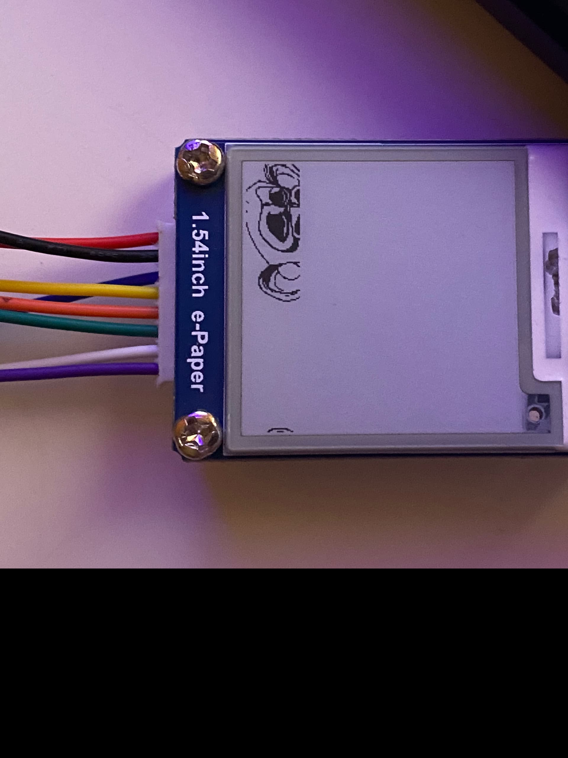
and this is what I see in my display:
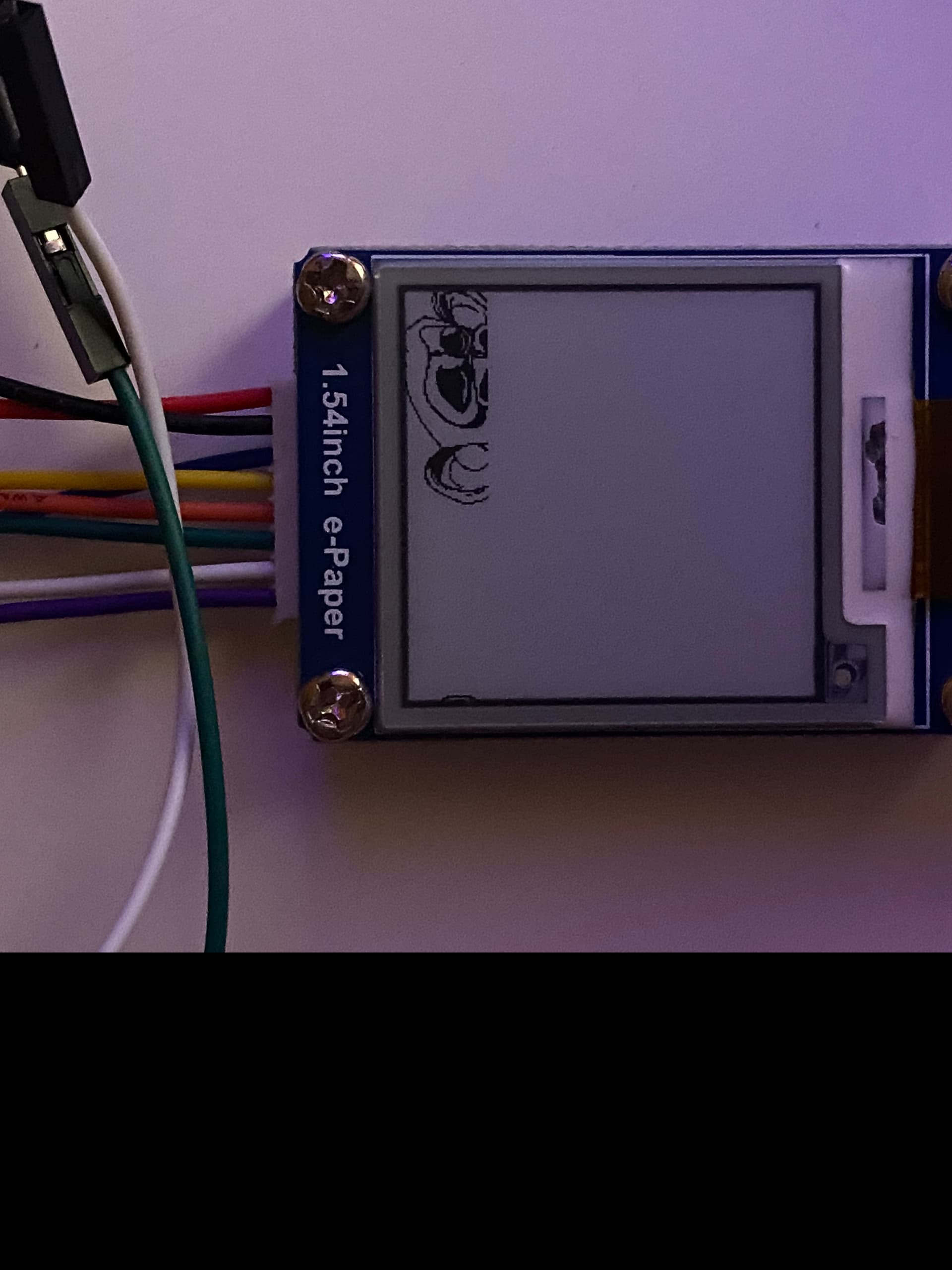
I tried using the examples provided with the library GxEPD2, but even if I'm using the correct wire connection, nothing happen on my screen and the only thing I see is the previous image with a black border like this:
My questions are: in draw() function I have to write the code of the image? Or, if it's possibile, can I store the image in display memory?
I'm using a wave share 1.54" b/w GDEH0154D67 with an Arduino MEGA2560
Thanks,
Alessio

 ]
]
