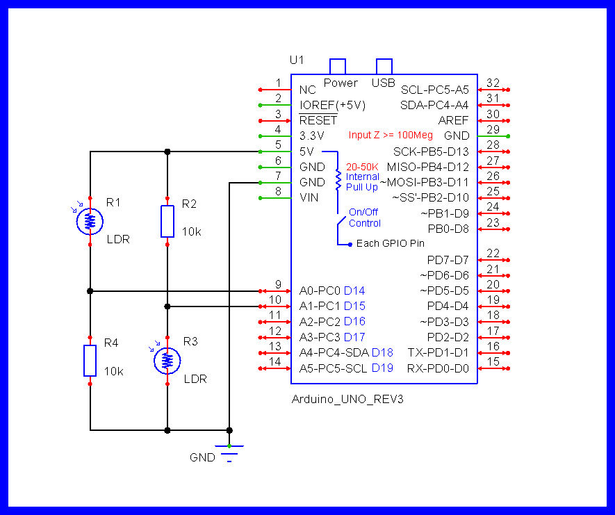
Hi guys,
Re :drag racing timing program :phototransistor sensors
I loaded a sketch into the Mega for this program :
My issue here per my cousin who is helping me, i have "no knowledge," just trying to learn, he is saying once we load the below sketch, pin 48, input, no voltage , but once we assign pin 48 to "start Lane 1, it goes " high ," and we have continuous voltage, given this is a phototransistor sensors , once the car goes over it he is stating it should trigger a "high and low".
But staying high, any suggestion on what to try to get this to work ?
#include <TM1637Display.h>

// Pines para los displays
#define CLK_REACCION_1 3
#define DIO_REACCION_1 2
#define CLK_CARRERA_1 6
#define DIO_CARRERA_1 7
#define CLK_REACCION_2 8
#define DIO_REACCION_2 9
#define CLK_CARRERA_2 11
#define DIO_CARRERA_2 10

// Pines para los sensores LDR
#define LDR_INICIO_CARRIL_1 A5
#define LDR_FINAL_CARRIL_1 A4
#define LDR_INICIO_CARRIL_2 A6
#define LDR_FINAL_CARRIL_2 A7

// Pines para los LEDs
#define LED_AMARILLO_CARRIL_1 A0
#define LED_VERDE_CARRIL_1 13
#define LED_ROJO_CARRIL_1 12
#define LED_AMARILLO_CARRIL_2 A3
#define LED_VERDE_CARRIL_2 A1
#define LED_ROJO_CARRIL_2 A2

// Pines para los pulsadores de Bracket
#define PULSADOR_BRACKET_CARRIL_1 5
#define PULSADOR_BRACKET_CARRIL_2 4

// Displays
TM1637Display displayReaccion1(CLK_REACCION_1, DIO_REACCION_1);
TM1637Display displayCarrera1(CLK_CARRERA_1, DIO_CARRERA_1);
TM1637Display displayReaccion2(CLK_REACCION_2, DIO_REACCION_2);
TM1637Display displayCarrera2(CLK_CARRERA_2, DIO_CARRERA_2);

// Variables globales
unsigned long tiempoInicioCarrera1 = 0;
unsigned long tiempoInicioCarrera2 = 0;
unsigned long tiempoReaccion1 = 0;
unsigned long tiempoReaccion2 = 0;
unsigned long tiempoCarrera1 = 0;
unsigned long tiempoCarrera2 = 0;
int bracket1 = 0;
int bracket2 = 0;
const int ldrInicio1 = A5;
const int ldrInicio2 = A6;
const int ldrFinal1 = A4;
const int ldrFinal2 = A7;
int valor0inicio1;
int valor0inicio2;
int valor0final1;
int valor0final2;
const int umbral = 50;

bool stage1 = false;
bool stage2 = false;
bool reaccionMedida1 = false;
bool reaccionMedida2 = false;
bool ledVerdeEncendido1 = false;
bool ledVerdeEncendido2 = false;
bool carreraFinalizada1 = false;
bool carreraFinalizada2 = false;

// Variables para la secuencia de luces
unsigned long tiempoInicioSecuencia = 0;
unsigned long tiempoDesdeStage1 = 0;  // Variable para contar el tiempo desde que ambos coches están en stage en el carril 1
unsigned long tiempoDesdeStage2 = 0;  // Variable para contar el tiempo desde que ambos coches están en stage en el carril 2
bool secuenciaEnProceso = false;
int estadoSecuencia1 = 0;
int estadoSecuencia2 = 0;

// Debounce variables
unsigned long lastDebounceTime1 = 0;
unsigned long lastDebounceTime2 = 0;
const unsigned long debounceDelay = 300;

// Variables para el intervalo de seguridad
unsigned long tiempoUltimaLecturaFinal1 = 0;
unsigned long tiempoUltimaLecturaFinal2 = 0;
const unsigned long intervaloSeguridad = 300; // 300 ms de intervalo de seguridad

// Variables para controlar si se debe seguir leyendo los LDR finales e iniciales
bool seguirLeyendoLDRFinal1 = true;
bool seguirLeyendoLDRFinal2 = true;
bool seguirLeyendoLDRInicio1 = true;
bool seguirLeyendoLDRInicio2 = true;

// Variables para detectar salida en falso
bool salidaEnFalsoDetectada1 = false;
bool salidaEnFalsoDetectada2 = false;

// Funciones
void setup() {
  // Inicialización de pines
  pinMode(LDR_INICIO_CARRIL_1, INPUT);
  pinMode(LDR_FINAL_CARRIL_1, INPUT);
  pinMode(LDR_INICIO_CARRIL_2, INPUT);
  pinMode(LDR_FINAL_CARRIL_2, INPUT);

  pinMode(LED_AMARILLO_CARRIL_1, OUTPUT);
  pinMode(LED_VERDE_CARRIL_1, OUTPUT);
  pinMode(LED_ROJO_CARRIL_1, OUTPUT);
  pinMode(LED_AMARILLO_CARRIL_2, OUTPUT);
  pinMode(LED_VERDE_CARRIL_2, OUTPUT);
  pinMode(LED_ROJO_CARRIL_2, OUTPUT);

  pinMode(PULSADOR_BRACKET_CARRIL_1, INPUT_PULLUP);
  pinMode(PULSADOR_BRACKET_CARRIL_2, INPUT_PULLUP);

  // Inicialización de displays
  displayReaccion1.setBrightness(2);
  displayCarrera1.setBrightness(2);
  displayReaccion2.setBrightness(2);
  displayCarrera2.setBrightness(2);

  // Inicialización de displays
  displayReaccion1.clear();
  displayCarrera1.clear();
  displayReaccion2.clear();
  displayCarrera2.clear();

  valor0inicio1 = analogRead(ldrInicio1);
  valor0inicio2 = analogRead(ldrInicio2);
  valor0final1 = analogRead(ldrFinal1);
  valor0final2 = analogRead(ldrFinal2);

  delay(1000);

  // Mostrar "0" al inicio en displays de tiempo de reacción
  displayReaccion1.showNumberDec(0);
  displayReaccion2.showNumberDec(0);
  displayCarrera1.showNumberDec(0);
  displayCarrera2.showNumberDec(0);

  // Manejar el tiempo de configuración del bracket
  manejarBracketConTiempo(60000); // Hasta 1 minuto para ajustar el bracket

  // Asegurarse de que los displays de tiempo de reacción muestren "0000" al finalizar el ajuste del bracket
  displayReaccion1.showNumberDec(0, true);
  displayReaccion2.showNumberDec(0, true);

  // Iniciar la secuencia de luces solo cuando ambos coches estén en stage
  while (!(stage1 && stage2)) {
    lecturasLDR(); // Actualizar el estado de los coches en stage
  }

  // Registrar el tiempo desde que ambos coches están en stage
  tiempoDesdeStage1 = millis();
  tiempoDesdeStage2 = millis();

  // Iniciar la secuencia de luces
  iniciarSecuenciaDeLuces();
}

void manejarBracketConTiempo(unsigned long tiempoMaximo) {
  unsigned long startTime = millis();
  unsigned long lastButtonPressTime = millis();

  while (millis() - startTime < tiempoMaximo) {
    if (millis() - lastButtonPressTime > 5000) {
      break; // Terminar si no se presiona ningún botón en 5 segundos
    }
    if (manejarBracket()) {
      lastButtonPressTime = millis(); // Actualizar el tiempo de la última pulsación de botón
    }
  }
}

bool manejarBracket() {
  bool buttonPressed = false;

  if (digitalRead(PULSADOR_BRACKET_CARRIL_1) == LOW) {
    if ((millis() - lastDebounceTime1) > debounceDelay) {
      bracket1 += 50;
      displayReaccion1.showNumberDec(bracket1, false);
      lastDebounceTime1 = millis();
      buttonPressed = true;
    }
  }

  if (digitalRead(PULSADOR_BRACKET_CARRIL_2) == LOW) {
    if ((millis() - lastDebounceTime2) > debounceDelay) {
      bracket2 += 50;
      displayReaccion2.showNumberDec(bracket2, false);
      lastDebounceTime2 = millis();
      buttonPressed = true;
    }
  }

  return buttonPressed;
}

void iniciarSecuenciaDeLuces() {
  secuenciaEnProceso = true;
  tiempoInicioSecuencia = millis();
}

void secuenciaDeLuces() {
  unsigned long currentMillis = millis();
  unsigned long tiempoSecuencia1 = 1000 + bracket1;
  unsigned long tiempoSecuencia2 = 1000 + bracket2;

  // Detectar salida en falso mientras está la secuencia en proceso
  int valor1inicio1 = analogRead(ldrInicio1);
  int valor1inicio2 = analogRead(ldrInicio2);

  if (!ledVerdeEncendido1 && !carreraFinalizada1 && stage1 && currentMillis - tiempoDesdeStage1 >= 1 && valor1inicio1 >= valor0inicio1) {
    salidaEnFalsoDetectada1 = true;
    digitalWrite(LED_ROJO_CARRIL_1, HIGH);
    digitalWrite(LED_VERDE_CARRIL_2, HIGH);
    digitalWrite(LED_AMARILLO_CARRIL_1, LOW);  // Apagar LED amarillo
    digitalWrite(LED_AMARILLO_CARRIL_2, LOW);  // Apagar LED amarillo
    displayReaccion1.showNumberDec(8888);
    displayCarrera1.showNumberDec(8888);
    displayReaccion2.showNumberDec(0, true);
    displayCarrera2.showNumberDec(0, true);
    return;
  }

  if (!ledVerdeEncendido2 && !carreraFinalizada2 && stage2 && currentMillis - tiempoDesdeStage2 >= 1 && valor1inicio2 >= valor0inicio2) {
    salidaEnFalsoDetectada2 = true;
    digitalWrite(LED_ROJO_CARRIL_2, HIGH);
    digitalWrite(LED_VERDE_CARRIL_1, HIGH);
    digitalWrite(LED_AMARILLO_CARRIL_1, LOW);  // Apagar LED amarillo
    digitalWrite(LED_AMARILLO_CARRIL_2, LOW);  // Apagar LED amarillo
    displayReaccion2.showNumberDec(8888);
    displayCarrera2.showNumberDec(8888);
    displayReaccion1.showNumberDec(0, true);
    displayCarrera1.showNumberDec(0, true);
    return;
  }

  if (secuenciaEnProceso) {
    // Manejar secuencia para carril 1
    switch (estadoSecuencia1) {
      case 0:
        if (currentMillis - tiempoInicioSecuencia >= tiempoSecuencia1) {
          digitalWrite(LED_AMARILLO_CARRIL_1, HIGH);
          estadoSecuencia1 = 1;
        }
        break;
      case 1:
        if (currentMillis - tiempoInicioSecuencia >= tiempoSecuencia1 + 400) {
          digitalWrite(LED_AMARILLO_CARRIL_1, LOW);
          digitalWrite(LED_VERDE_CARRIL_1, HIGH);
          ledVerdeEncendido1 = true;
          tiempoInicioCarrera1 = millis();
          estadoSecuencia1 = 2;
        }
        break;
    }

    // Manejar secuencia para carril 2
    switch (estadoSecuencia2) {
      case 0:
        if (currentMillis - tiempoInicioSecuencia >= tiempoSecuencia2) {
          digitalWrite(LED_AMARILLO_CARRIL_2, HIGH);
          estadoSecuencia2 = 1;
        }
        break;
      case 1:
        if (currentMillis - tiempoInicioSecuencia >= tiempoSecuencia2 + 400) {
          digitalWrite(LED_AMARILLO_CARRIL_2, LOW);
          digitalWrite(LED_VERDE_CARRIL_2, HIGH);
          ledVerdeEncendido2 = true;
          tiempoInicioCarrera2 = millis();
          estadoSecuencia2 = 2;
        }
        break;
    }

    // Si ambas secuencias han terminado
    if (estadoSecuencia1 == 2 && estadoSecuencia2 == 2) {
      secuenciaEnProceso = false;
    }
  }
}

void lecturasLDR() {
    if (salidaEnFalsoDetectada1 || salidaEnFalsoDetectada2) {
        return;  // Si se ha detectado una salida en falso en algún carril, detener todos los procesos
    }

    unsigned long currentMillis = millis();

    int valor1inicio1 = analogRead(ldrInicio1);
    int valor1inicio2 = analogRead(ldrInicio2);
    int valor1final1 = analogRead(ldrFinal1);
    int valor1final2 = analogRead(ldrFinal2);

    // Detectar si los coches están en stage
    if (seguirLeyendoLDRInicio1 && valor1inicio1 < valor0inicio1 - umbral) {
        stage1 = true;
        displayCarrera1.showNumberDec(0, true);
    }

    if (seguirLeyendoLDRInicio2 && valor1inicio2 < valor0inicio2 - umbral) {
        stage2 = true;
        displayCarrera2.showNumberDec(0, true);
    }

    // Detectar salida en falso para carril 1
    if (!ledVerdeEncendido1 && !carreraFinalizada1 && stage1 && currentMillis - tiempoDesdeStage1 >= 1 && valor1inicio1 >= valor0inicio1) {
        salidaEnFalsoDetectada1 = true;
        digitalWrite(LED_ROJO_CARRIL_1, HIGH);
        digitalWrite(LED_VERDE_CARRIL_2, HIGH);
        displayReaccion1.showNumberDec(8888);
        displayCarrera1.showNumberDec(8888);
        displayReaccion2.showNumberDec(0, true);
        displayCarrera2.showNumberDec(0, true);
        return;
    }

    // Detectar salida en falso para carril 2
    if (!ledVerdeEncendido2 && !carreraFinalizada2 && stage2 && currentMillis - tiempoDesdeStage2 >= 1 && valor1inicio2 >= valor0inicio2) {
        salidaEnFalsoDetectada2 = true;
        digitalWrite(LED_ROJO_CARRIL_2, HIGH);
        digitalWrite(LED_VERDE_CARRIL_1, HIGH);
        displayReaccion2.showNumberDec(8888);
        displayCarrera2.showNumberDec(8888);
        displayReaccion1.showNumberDec(0, true);
        displayCarrera1.showNumberDec(0, true);
        return;
    }

    // Detectar tiempo de reacción
    if (ledVerdeEncendido1 && !reaccionMedida1 && valor1inicio1 >= valor0inicio1) {
        tiempoReaccion1 = currentMillis - tiempoInicioCarrera1;
        displayReaccion1.showNumberDecEx(tiempoReaccion1, 0b10000000, true);
        reaccionMedida1 = true;
        seguirLeyendoLDRInicio1 = false;  // Dejar de leer el LDR de inicio
    }

    if (ledVerdeEncendido2 && !reaccionMedida2 && valor1inicio2 >= valor0inicio2) {
        tiempoReaccion2 = currentMillis - tiempoInicioCarrera2;
        displayReaccion2.showNumberDecEx(tiempoReaccion2, 0b10000000, true);
        reaccionMedida2 = true;
        seguirLeyendoLDRInicio2 = false;  // Dejar de leer el LDR de inicio
    }

    // Detectar fin de carrera con intervalo de seguridad
    if (ledVerdeEncendido1 && seguirLeyendoLDRFinal1 && valor1final1 < valor0final1 - umbral) {
        if (currentMillis - tiempoUltimaLecturaFinal1 > intervaloSeguridad) {
            tiempoCarrera1 = currentMillis - tiempoInicioCarrera1;
            displayCarrera1.showNumberDecEx(tiempoCarrera1, 0b10000000, true);
            seguirLeyendoLDRFinal1 = false;
            ledVerdeEncendido1 = false;
            carreraFinalizada1 = true;
            digitalWrite(LED_VERDE_CARRIL_1, LOW);

            // Verificar si es el primer coche en cruzar la meta
            if (!carreraFinalizada2) {
                digitalWrite(LED_VERDE_CARRIL_1, HIGH);  // Encender LED verde del carril 1
            }
        }
        tiempoUltimaLecturaFinal1 = currentMillis;
    }

    if (ledVerdeEncendido2 && seguirLeyendoLDRFinal2 && valor1final2 < valor0final2 - umbral) {
        if (currentMillis - tiempoUltimaLecturaFinal2 > intervaloSeguridad) {
            tiempoCarrera2 = currentMillis - tiempoInicioCarrera2;
            displayCarrera2.showNumberDecEx(tiempoCarrera2, 0b10000000, true);
            seguirLeyendoLDRFinal2 = false;
            ledVerdeEncendido2 = false;
            carreraFinalizada2 = true;
            digitalWrite(LED_VERDE_CARRIL_2, LOW);

            // Verificar si es el primer coche en cruzar la meta
            if (!carreraFinalizada1) {
                digitalWrite(LED_VERDE_CARRIL_2, HIGH);  // Encender LED verde del carril 2
            }
        }
        tiempoUltimaLecturaFinal2 = currentMillis;
    }
}

void loop() {
  if (salidaEnFalsoDetectada1 || salidaEnFalsoDetectada2) {
    return;  // Si se ha detectado una salida en falso en algún carril, detener el loop
  }

  if (secuenciaEnProceso) {
    secuenciaDeLuces();
  } else {
    lecturasLDR();
  }
}