My first time in here after weeks of getting through troubles on my own. The quantity of data and help is just crazy and I would like to thank everybody for it!
Unfortunately, this time it gets more difficult!
Let me try giving most of the details in order to keep focusing on the issue!
During motor movements, the CNC shield power supply keeps steady at 30VDC without any visible trouble.
During "locking" and motor movements, the power supply supplies less than 1A.
Motors are turning without any kind of load.
Expected behaviour
When using the KY-023 Joystick, I aim having motors stepping accordingly to the analog reading.
Left / Right would be X axis clockwise and counter clockwise ; Top / Bottom would be Y axis clockwise and counter clockwise .
The further I push the joystick, the faster the motors steps.
Extra care
Joytstick imperfections are handled by the soft: Min, Mid and Max values as well as some kind of mechanical play.
I did the math with all my variables to make sure I calculate the right speed for a given joystick position.
The issue!!
Axis movements aren't smooth if I am not pushing the joystick to its maximum. I have some kind of vibration as well as some steps in the wrong direction.
Motors sort of sing / vibrate even when "locked". They get silent when I unplug the Enable pin and torque is lost.
I tried change Min and Max speeds, it's the same.
I tried to add some delay in the end of each loop, it failed as well.
Wiring
(DRV and Arduino for illustrative purposes only, everything is plugged.)
// Pin numbers
const int X_pin = A0; // analog pin connected to X output ; A0
const int Y_pin = A1; // analog pin connected to Y output ;  A1

// Handling X-axis joystick defects
float Xmin = 0; // full left, should be 0
float ZeroX = 510; // middle point, should be 512
float Xmax = 1023; // full right, should be 1024
float OffsetX = 100; // Handling middle mechanical play at middle point
// Handling Y-axis joystick defects
float Ymin = 0; // full bottom, should be 0
float ZeroY = 490; // middle point, should be 512
float Ymax = 1023; // full top, should be 1024
float OffsetY = 100; // Handling middle mechanical play at middle point

// X axis values
float VitX = 0; // 0 = Stop ; 1 = Full Speed
float DirX = 0; // 0 = Stop ; 1 = Clockwise ("Right") ; -1 = CounterClockwise ("Left")
float X = 0; // from 0 to 1024, X joystick position

// Y axis values
float VitY = 0; // 0 = Stop ; 1 = Full Speed
float DirY = 0; // 0 = Stop ; 1 = Clockwise ; -1 = CounterClockwise
float Y = 0; // from 0 to 1024, Y joystick position

// Motors control parameters
const float DelayXmax = 7000; // Min speed for X axis
const float DelayXmin = 500; // Max speed for X axis
const float DelayYmax = 7000; // Min speed for Y axis
const float DelayYmin = 500; // Max speed for Y axis

// Stepper motor X speed variable
float SMspeedX = (DelayXmax+DelayXmin)/2;

// Stepper motor Y speed variable
float SMspeedY = (DelayYmax+DelayYmin)/2;

// Motors display management
// Let's assume VminX = VminY = 0, these variable wont be used in the sketch
float VmaxX = 100; // arbitrary
float VmaxY = 100; // arbitrary

// Motors' outputs
const int stepPinX = 2; //X.STEP output
const int dirPinX = 5; // X.DIR output

// Motors output
const int stepPinY = 3; //Y.STEP output
const int dirPinY = 6; // Y.DIR output

//######################################################

void setup() {
  // Pins to read from Joystick
  pinMode(X_pin, INPUT);
  pinMode(Y_pin, INPUT);

  // Pins to digitalWrite for Motor X
  pinMode(stepPinX,OUTPUT);
  pinMode(dirPinX,OUTPUT);

  // Pins to digitalWrite for Motor Y
  pinMode(stepPinY,OUTPUT);
  pinMode(dirPinY,OUTPUT);

  //Monitoring and debugging
  Serial.begin(115200);
}

//######################################################

void loop() {
  //---------------------------------------------------
  // Reading X value
  X = analogRead(X_pin);

  // Calc X Dir
  if (X < ZeroX-OffsetX) {DirX = -1;}
  else if (X > ZeroX+OffsetX) {DirX = 1;}
  else {DirX = 0;}

  // Calc X Speed to debug purposes only
  if (X < ZeroX-OffsetX) {VitX = (VmaxX/(Xmin-ZeroX+OffsetX)*X+VmaxX/((Xmin/(OffsetX-ZeroX))+1));}
  else if (X > ZeroX+OffsetX) {VitX = (VmaxX/(Xmax-ZeroX-OffsetX))*X+(VmaxX/(1-(Xmax/(ZeroX+OffsetX))));}
  else {VitX = 0;}


  // Move X StepperMotor
  if (DirX == 1) {
    StepRightX();
    //Serial.println(SMspeedX);
    }
  else if (DirX == -1) {
    StepLeftX();
    //Serial.println(SMspeedX);
    }
  else {}


  //---------------------------------------------------
  // Reading Y value
  Y = analogRead(Y_pin);

  // Calc Y Dir
  if (Y < ZeroY-OffsetY) {DirY = -1;}
  else if (Y > ZeroY+OffsetY) {DirY = 1;}
  else {DirY = 0;}

  // Calc Y Speed to debug purposes only
  if (Y < ZeroY-OffsetY) {VitY = (VmaxY/(Ymin-ZeroY+OffsetY)*Y+VmaxY/((Ymin/(OffsetY-ZeroY))+1));}
  else if (Y > ZeroY+OffsetY) {VitY = (VmaxY/(Ymax-ZeroY-OffsetY))*Y+(VmaxY/(1-(Ymax/(ZeroY+OffsetY))));}
  else {VitY = 0;}


  // Move Y StepperMotor
  if (DirY == 1) {
    StepRightY();
    //Serial.println(SMspeedY);
    }
  else if (DirY == -1) {
    StepLeftY();
    //Serial.println(SMspeedY);
    }
  else {}

  //---------------------------------------------------

  //delay(1); //Used to try to smooth movements

  return;

  // Display X
  Serial.print("X measurement:");
  Serial.print(X);
  Serial.println();
  Serial.print("VitX = ");
  Serial.print(VitX);
  Serial.println();
  Serial.print("DirX = ");
  Serial.print(DirX);
  Serial.println();
  Serial.print("X delay : ");
  Serial.print(SMspeedX);
  Serial.println();
  Serial.println();


  // Display Y
  Serial.print("Y measurement:");
  Serial.print(Y);
  Serial.println();
  Serial.print("VitY = ");
  Serial.print(VitY);
  Serial.println();
  Serial.print("DirY = ");
  Serial.print(DirY);
  Serial.println();
  Serial.print("Y delay : ");
  Serial.print(SMspeedY);
  Serial.println();
  Serial.println();


  // Delay to make Serial readable
  //delay(500);

}

//######################################################


void StepRightX(){
    // Calc X micro-delay to drive stepper motor X clockwise at a given speed
    SMspeedX = ((DelayXmin-DelayXmax)/(Xmax-ZeroX-OffsetX))*X+((Xmax*DelayXmax-DelayXmin*(ZeroX+OffsetX))/(Xmax-ZeroX-OffsetX));

    //Stepping motor
    digitalWrite(dirPinX,LOW);
    digitalWrite(stepPinX,HIGH);
    delayMicroseconds(SMspeedX);
    digitalWrite(stepPinX,LOW);
    delayMicroseconds(SMspeedX);
  }

void StepLeftX(){
    // Calc X micro-delay to drive stepper motor X counter clockwise at a given speed
    SMspeedX = ((DelayXmax-DelayXmin)/(ZeroX-OffsetX-Xmin))*X+((ZeroX-OffsetX)*DelayXmin-Xmin*DelayXmax)/(ZeroX-OffsetX-Xmin);

    digitalWrite(dirPinX,HIGH);
    digitalWrite(stepPinX,HIGH);
    delayMicroseconds(SMspeedX);
    digitalWrite(stepPinX,LOW);
    delayMicroseconds(SMspeedX);
  }

//-----------------------------------------

void StepRightY(){
    // Calc Y micro-delay to drive stepper motor Y clockwise at a given speed
    SMspeedY = ((DelayYmin-DelayYmax)/(Ymax-ZeroY-OffsetY))*Y+((Ymax*DelayYmax-DelayYmin*(ZeroY+OffsetY))/(Ymax-ZeroY-OffsetY));

    //Stepping motor
    digitalWrite(dirPinY,LOW);
    digitalWrite(stepPinY,HIGH);
    delayMicroseconds(SMspeedY);
    digitalWrite(stepPinY,LOW);
    delayMicroseconds(SMspeedY);
  }

void StepLeftY(){
    // Calc Y micro-delay to drive stepper motor Y counter clockwise at a given speed
    SMspeedY = ((DelayYmax-DelayYmin)/(ZeroY-OffsetY-Ymin))*Y+((ZeroY-OffsetY)*DelayYmin-Ymin*DelayYmax)/(ZeroY-OffsetY-Ymin);

    digitalWrite(dirPinY,HIGH);
    digitalWrite(stepPinY,HIGH);
    delayMicroseconds(SMspeedY);
    digitalWrite(stepPinY,LOW);
    delayMicroseconds(SMspeedY);
  }
I thank you in advance for your help in this hard quest of the wobbling / shaking motors that I'm sure are not possessed by the devil!
I think you are making the mistake of doing to much at once. When you develop a project take it one step at a time.
First just write some code that will print the output from your joystick. Use the serial plotter to see a visualisation of the output and see if this is jittery or not. Don't move on until you have a good reading. If necessary if you can't get a steady reading there are both hardware and software ways of fixing this problem.
Then when you have a good output go on to trying to drive your motors.
A word of caution
That implies some sort of power problem, perhaps caused by lack of supply decoupling. It happens on a servo but should not happen on a stepping motor unless some sort of positional feedback is being used.
Also singing if a motor when it moves is caused by mechanical resonance of the motors and their mountings. The best way to cure that is by using micro stepping the motor.
As well as the suggestions from @Grumpy_Mike, analog joysticks often benefit from having a 0.1uF -1uF cap from the wiper to ground to bypass noise to ground.
Well I tried my 2 joysticks on a Arduino Mega 2560 board (the Uno + CNC won't be online before tomorrow).
I get some interferances that look pretty low and acceptable to me. And they occur only when to joystick leave its middle point area, perhaps a little bit more on one of the joysticks.
I think so, but it costs next to nothing to try. I always put a cap (0.1uF ceramic) from the wiper to ground and it always helps to quiet down the higher frequency noise.
That blue joystick trace is pretty crappy. I would probably replace it. A cap may not be of that much help.
I would agree with that and add that both waveforms look poor. This is a hardware problem with the joystick you have. What is the pot value in them? They are very noisy. Maybe you could try a squirt of IPA to clean up the track inside the pot. Also use some electrolube to lubricate the moving parts of the pot.
Yes a capacitor would help as would taking a few readings and average them before printing them out, but that is a sticking plaster on the problem.
Also try printing out a 1024 every time so the scale on the serial plot always has the same scale.
Yeah, i did not realize that the traces were zoomed so much till @Grumpy_Mike pointed it out. The Y axis labels are so small that I couldn't read them. Still a cap and averaging can help if there is noise.
That last one you posted, did the movement of the joystick follow the curves?
It looks like on two occasions like the pot was moved to an extreme position and the curve goes to the limit for a short time and then continues in the negative direction.
Or does it follow your pot movement?
Anyway it looks to me that those later curves are a lot better than the first ones, and the improvement is not simply due the the scale.
Actually, the pot hit its max value before the joystick itself comes to its mechanical stop.
So if I go up smoothly, hit maximum briefly and goes down just afterwards, I won't have a sine shaped signal but something that looks like a triangle signal with its top flatted.
On the first curves, I was gently moving the joystick, as slow as possible, to find out if there is any unexpected behavior.
On the new curves, there is still no cap: I was moving the joystick as I would during working on the finished project.
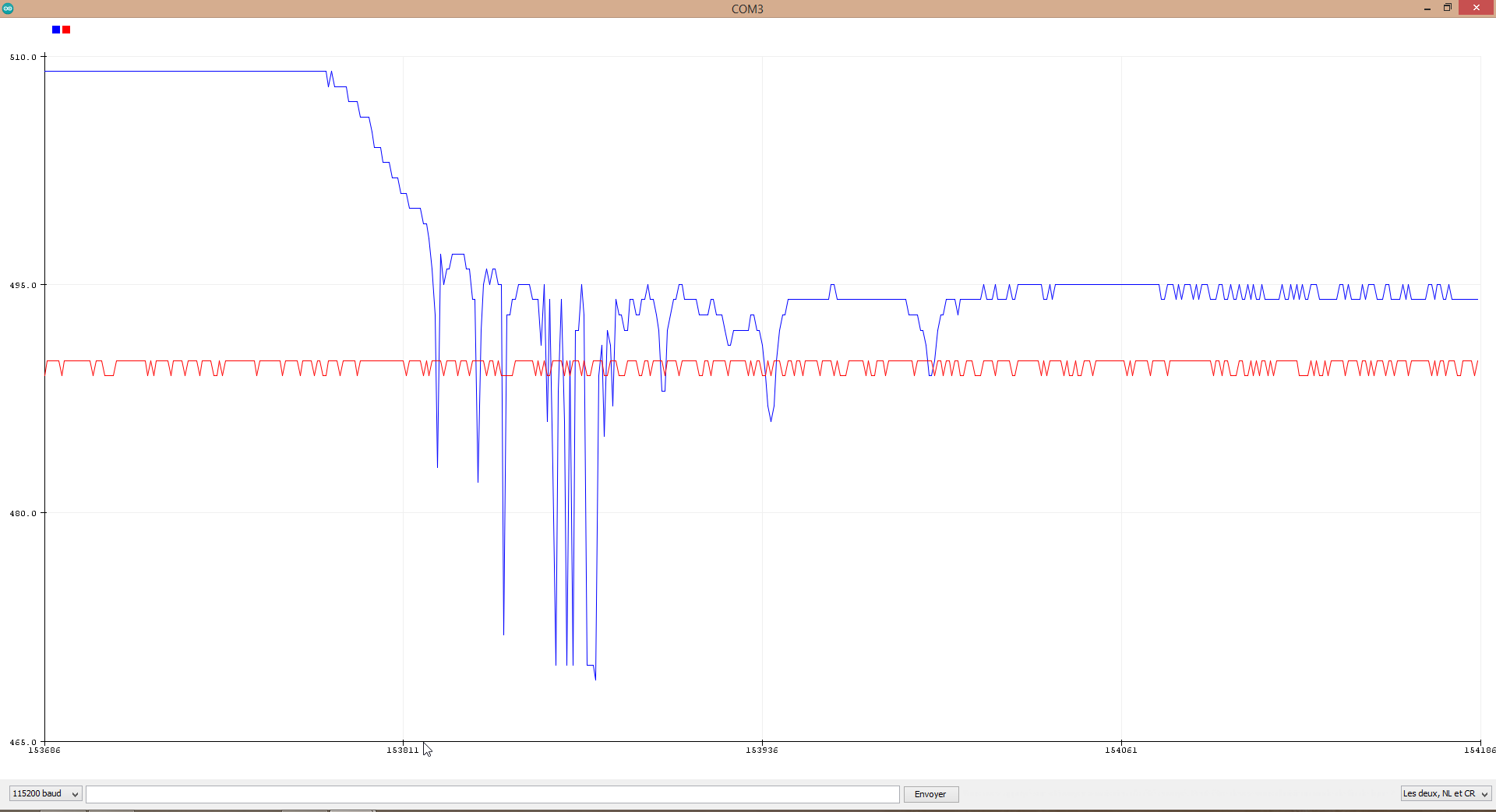
It actually does a little bit when I touch pins behind the joystick PCB by hand. No more than 1 or 2 units. On heavily zoomed screenshot below: touching pins then not touching them.
Do you think the joystick itself has any problem? Beside its offsets for min, mid and max values + its gap between mechanical and electronical max, it looks fine to me. These points seems expectable for such a cheap component.
Not sure, how is the joystick connections to the Arduino made? Do they go through a solderless bread board or are they soldered? It could be noise induced by a slight intermittent connection, caused by your movement as you hold the joystick.
There indeed was, but it remains pretty low and the signal to noise ratio remains favorable in my opinion.
I only used Female - Male jumpers, nothing is soldered for now. I tried to shake the whole thing during a test today, to be honnest it did not induced any problem.
Hi TomGerorge, here are requested items. Blue and Red are X and Y axis.
Thanks for that.
Could you make a measurement for us. Remove the joystick from all connections with the Arduino and then measure the resistance between the 5V and ground of the joystick. This hopefully will give the resistance of the pots. A value greater than 50K or so would indicate a problem interacting with the Arduino.
I didn't know what others think but it maybe time to consider the bit that doesn't make sense:-
This shouldn't happen. It might indicate something wrong with the wiring or the driver. Is it possible to just wire the motor up and give it a slow ramp rather than take the speed from the joystick.
The thing about an A/D converter is that it is always +/- 1 least significant bit out due to noise. This applies to all A/D converters and not just the one in the Uno. As you are using the current reading to control your motor that noise will show itself with exactly what you are seeing. Namely:-
It is this least significant bit of noise that is causing this singing as the motor moves rapidly to match this noise. A way round this involves using the technique of hysteresis, where you move only when there has been a significant change since the last reading.
This is some code that illustrates the solution. I originally wrote it for pots to send MIDI control messages without swamping the MIDI channel with repeat messages. I have put the number of pots to two and you can see the results in the plot window. Note that for MIDI messages the range is restricted to between 0 and 127, that is a six bit number, and thinking about it that should be fine for your motor.
// Pots to MIDI control message value range with hysteresis
// view with serial plotter
// Arduino Uno / Nano

const byte numberOfPots = 2;
int rawReading [numberOfPots];
int lastReading [numberOfPots];

void setup() {
Serial.begin(115200);
}

void loop() {
  for(int i = 0; i<numberOfPots; i++){ // get the readings
   rawReading[i] = analogRead(i);
  }
  for(int i = 0; i<numberOfPots; i++){
    if(abs(lastReading[i] - rawReading[i]) >=7){ // the hysteresis bit
       Serial.print(rawReading[i] >> 3); // reduce to the range 0 to 127
       Serial.print("\t");                            // print the new value
       lastReading[i] = rawReading[i];
    }
    else { // if there has not been enough change in the readings from the pots
    Serial.print(lastReading[i] >>3);
    Serial.print("\t");
    }
  }
    Serial.println();
    delay(50);
}
I think if you incorporate this technique in your original code things will be a lot better.
Sorry for not spotting this before now.
Sorry guys for the late reply. Hard week and busy weekend..!
To be honnest, I'm just following the wiring diagram I have in the learning book I got with the starter pack !
That's what I've done, didn't I?
I measure a nice 4.8KOhm. That actually is a very common component, delivered with a well reviewed newbie kit on Amazon.
I don't understand why because my initial sketch do not do anything if the read value do not go further a certain offset. According to me a +/-2 units of noise can not do anything due to the fact that I expect a value of at least +/- 100 in my sketch (the offset). Please see graph below:
Stop thinking you are right all the time. Your code is appalling, hard to follow and uses floats all over the place.
But if you continue with your attitude and refuse to contemplate you could have made a mistake you will keep on making it.
Have you tried all the things I said? Especially
Did you try that?
Did you try putting the hysteresis code I gave you?
I know why I could do next and that is to stop trying to help you because from my end it seems like a waste of time. Unless you are willing to cooperate.
I am very sorry my answers make you think this way. This is obviously not my point as I try to understand what I did wrong and what I could do to improve.
If I were experienced, my code wouldn't be appalling. I am quite aware of that.
I try my best to provide details, clean graphs, drawings and a code as much commented as I could to make it easier for this board's members and helpers. Nevertheless, I agree, it certainly is not perfect.
If I may, let me try to provide more feedbacks.
I may have misunderstood what you are expecting. I tried the sketch below. I hope this will match your request?
 // Stepper Motor X
  const int stepPin = 2; //X.STEP
  const int dirPin = 5; // X.DIR

 void setup() {
 // Sets the two pins as Outputs
 pinMode(stepPin,OUTPUT);
 pinMode(dirPin,OUTPUT);
 }
 void loop() {
 digitalWrite(dirPin,HIGH); // Enables the motor to move in a particular direction
 // Makes 200 pulses for making one full cycle rotation
 for(int x = 0; x < 200; x++) {
 digitalWrite(stepPin,HIGH);
 delayMicroseconds(500);
 digitalWrite(stepPin,LOW);
 delayMicroseconds(500);
 }
 delay(1000); // One second delay

 digitalWrite(dirPin,LOW); //Changes the rotations direction
 // Makes 400 pulses for making two full cycle rotation
 for(int x = 0; x < 400; x++) {
 digitalWrite(stepPin,HIGH);
 delayMicroseconds(500);
 digitalWrite(stepPin,LOW);
 delayMicroseconds(500);
 }
 delay(1000);
 }
In case I understood your request properly:
It works well and smoothly. Motors seems to follow accurate movements.
(By the way, I just uploaded the BareMinimum sketch, that includes stricly nothing more than empty Setup and Loop. As soon as I ground the Enable pin from the CNC shield, motor start singing on the table, I can also hear it if I put my ear on the motor.)
Yes I did. It plots nice curves that looks like the second batch I uploaded, at a 0-127 scale. The noise on the middle position is gone, of course.