3 Potentiometers, Arduino Pro Micro & OLED - VCC Chain cause Arduino shut off

Hey all, new here, new to Arduino.
Just need someone to shed some light here.
Have 3 Alps Alpine Faders, OLED screen and Arduino Pro Micro.
This setup worked perfectly on a breadboard but once it was time for soldering. I ran into issues with the Arduino not powering on when all connected.

After troubleshooting I found the VCC from the fader chain is causing the issue and possibly the chaining of the ground from the faders
See below how I've wired it

Can anyone one confirm if this is correct?

Also not confident on how the wires should go on the fader terminals for chaining together, so any help on that would be really appreciated too. Cheers

Looking at the Terminal Layout / Circuit Diagram taken from https://tech.alpsalpine.com/e/products/detail/RSA0N1219A03/
product_detail_fig_rsn_c_2_en_29a6519959
It looks as though you have got the connections correct.

1 Like

I would agree, if the pins are represented as per the spec, it looks like you wired like this

image

which sound reasonable although it's always best to wire GND directly (star versus daisy chain)

Thanks for response, so solder all 4 ground sources to the one ground on the Arduino? I'll give that a try tommorow.

Would that be best to do for VCC (5V) as well?

Yes 5V not more as this is what you arduino can deal with.
what's you OLED ?

Alright cool, I'll try star joint with VCC as well.

Here's the page for the OLED

To be fair given the simplicity of your wiring and the fact that there is no motor or inductance that’s not where the issue is.

Do you have a DMM?

Can you confirm the exact model of your faders ? (Resistance)

Can you share the testing code you use?

Your screen is using I2C, it should not be connected on pin 2 and 3 but A4 (SDA) and A5 (SCL).

Nah dont have a Multimeter, Will need to pick one up soon though.

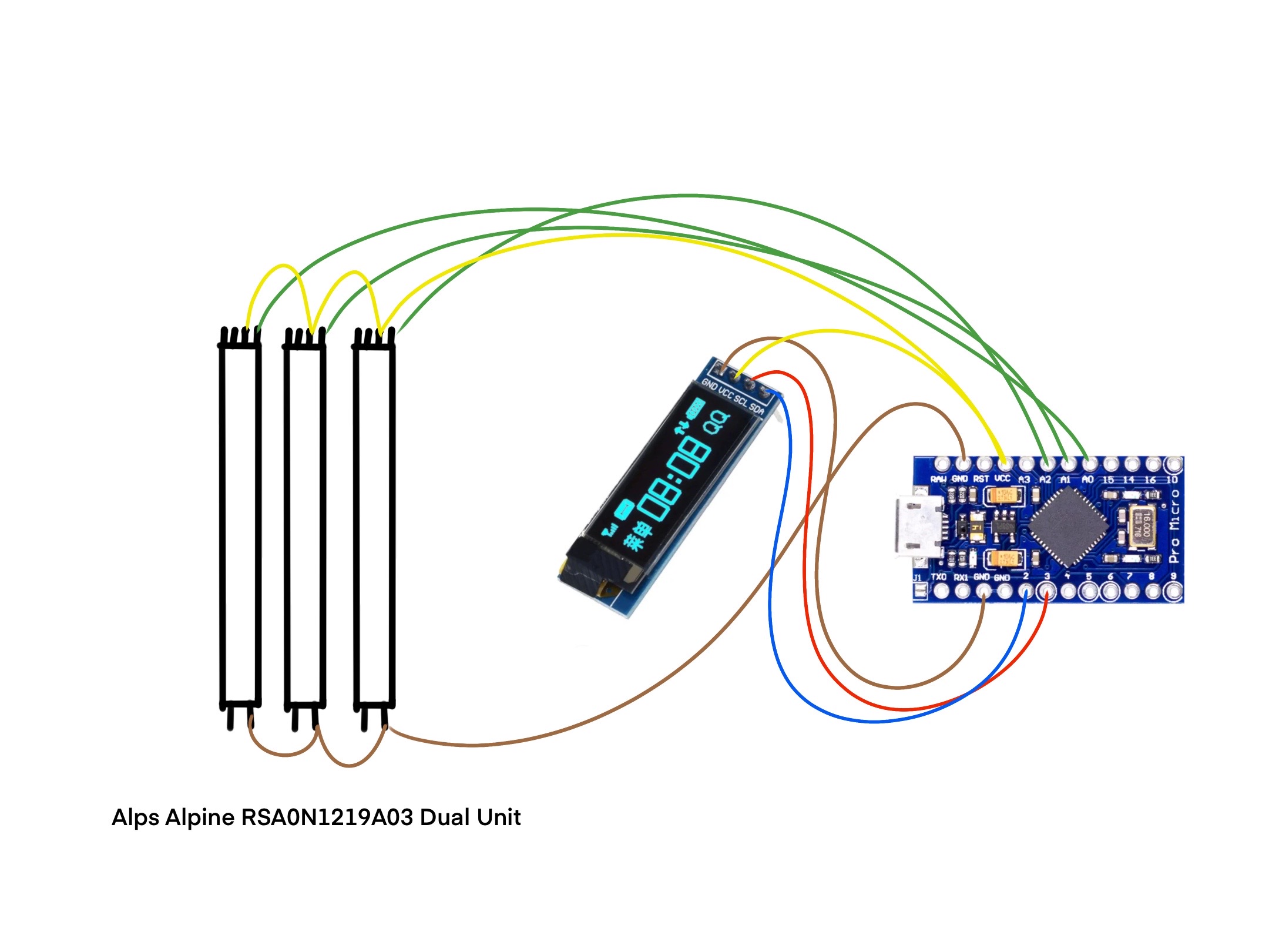
Exact Model Of Fader and Spec's Below in the page below

CODE BELOW:

#include "MIDIUSB.h" // Include the MIDIUSB library for MIDI Communication
#include <ResponsiveAnalogRead.h> 

#include <Wire.h>
#include <Adafruit_GFX.h>
#include <Adafruit_SSD1306.h>

// Define pins for OLED display
#define OLED_RESET 4
#define SCREEN_WIDTH 128
#define SCREEN_HEIGHT 32

// Initialize OLED display
Adafruit_SSD1306 display(SCREEN_WIDTH, SCREEN_HEIGHT, &Wire, OLED_RESET);

// Define MIDI channel
#define MIDI_CHANNEL 1

// Define analog input pins
#define DYN A0
#define EXP A1
#define VIB A2


#define LOGO_HEIGHT   16;
#define LOGO_WIDTH    16;


// Fader Pin & State
const int N_POTS = 3;

int potPin[N_POTS] = { A0, A1, A2 };
int potCC[N_POTS] = { 11, 1, 21 };

int potReading[N_POTS] = { 0 };
int potState[N_POTS] = { 0 };
int potPState[N_POTS] = { 0 };

int midiState[N_POTS] = { 0 };
int midiPState[N_POTS] = { 0 };

const byte potThreshold = 15;
const int POT_TIMEOUT = 300;
unsigned long pPotTime[N_POTS] = {0};
unsigned long potTimer[N_POTS] = {0};

byte POT_CH = 0;

float snapMultiplier = 0.01;
ResponsiveAnalogRead responsivePot[N_POTS] = {};

void setup() {
  // TEXT DISPLAY
  ;display.clearDisplay();
  ;display.setTextSize(2);
  ;display.setTextColor(WHITE);
  ;display.setCursor(4,30);
  ;display.print("Lothrian-3");
  ;display.display();
  Serial.begin(9600);

  for(int i = 0; i <N_POTS; i++) {
    responsivePot[i] = ResponsiveAnalogRead(0, true, snapMultiplier);
    responsivePot[i].setAnalogResolution(1023);  

  // Initialize serial communication
  Serial.begin(9600);

  // Initialize OLED display
  display.begin(SSD1306_SWITCHCAPVCC, 0x3C);
  display.clearDisplay();

  // Set text size and color for display
  display.setTextSize(2);
  display.setTextColor(WHITE);

  }  
}

void loop() {
  // put your main code here, to run repeatedly:


  for (int i = 0; i < N_POTS; i++) {

    potReading[i] = analogRead(potPin[i]); 
    responsivePot[i].update(potReading[i]);
    potState[i] = responsivePot[i].getValue();
    midiState[i] = map(potState[i], 0, 1023, 0, 128);

    int potVar = abs(potState[i] - potPState[i]);

    if (potVar > potThreshold) {
      pPotTime[i] = millis();
    } 

    potTimer[i] = millis() - pPotTime[i];


if(potTimer[i] < POT_TIMEOUT) {
    if (midiState[i] != midiPState[i]) {

      controlChange(POT_CH, potCC[i], midiState[i]);
      MidiUSB.flush();

      Serial.print("Pot ");
      Serial.print(i);
      Serial.print(" | ");
      Serial.print("potState: ");
      Serial.print(potState[i]);
      Serial.print(" - midiState:");
      Serial.println(midiState[i]);

      midiPState[i] = midiState[i];
     } 
    potPState[i] = potState[i];

  // Read analog inputs and map values to MIDI range (0-127)
  int analogValue1 = map(analogRead(DYN), 0, 1023, 0, 127);
  int analogValue2 = map(analogRead(EXP), 0, 1023, 0, 127);
  int analogValue3 = map(analogRead(VIB), 0, 1023, 0, 127);


  // Display analog values on OLED display
  display.clearDisplay();
  display.setCursor(0, 19);
  display.print("EXP ");
  display.setCursor(0, 0);
  display.println(analogValue1);

  display.setCursor(48, 19);
  display.print("DYN ");
  display.setCursor(48, 0);
  display.println(analogValue2);
  
  display.setCursor(92, 19);
  display.print("VIB ");
  display.setCursor(92, 0);
  display.println(analogValue3);
  display.display();

  // Delay for stability
  delay(1);
    } 
  }
}


void noteOn(byte channel, byte pitch, byte velocity) {
  midiEventPacket_t noteOn = {0x09, 0x90 | channel, pitch, velocity};
  MidiUSB.sendMIDI(noteOn);
}

void noteOff(byte channel, byte pitch, byte velocity) {
  midiEventPacket_t noteOff = {0x08, 0x80 | channel, pitch, velocity};
  MidiUSB.sendMIDI(noteOff);
}

void controlChange(byte channel, byte control, byte value) {
  midiEventPacket_t event = {0x0B, 0xB0 | channel, control, value};
  MidiUSB.sendMIDI(event);
}

please read How to get the best out of this forum and post your code with code tags.

I corrected your previous post for this time.

1 Like

aren't they meant for AC usage ?

Thanks for all your help on this man.

Ah okay, they are AC Usage, So I'll need to get a different Arduino that has additional AC power, Such as an Arduino UNO?

I don't know of an Arduino that deals with AC

I'm not an hardware expert so I don't know what specifically makes this an AC component and what it's supposed to do if you get a DC input to it.

There are simple slide potentiometers that you can use with your arduino

Hi, @J-M-L

How do you mean the potentiometers are meant for AC?
350Vac operating, but they are resistors, what does AC or DC have to do with how they operate?

350Vac across a 10K resistor = 350 / 10,000 = 35mArms
Power rating = 350 x350 / 10,000 = 12.5WattsRMS

The only reason for an AC rating is for audio use.

The specs are confusing as the slider is rated at 0.25W.

@hollowdrive desperately needs to get a DMM before continuing.

Tom.. :smiley: :+1: :coffee: :australia:

That was more a question rather than an affirmation.The spec only mentions AC, hence I was wondering if they are special in some way.

edit: actually I did not read far enough, the spec does mention DC too

so DMM needed to see what's going on

Thanks for all your help guys, I'll pick up a DMM tommorow and let you know the results

Hey All,

Just an update and i hope this helps someone else out, but I no longer have any issues with arduino powering off. All connected, My issue was an obvious one... Bad Soldering.

Some of my solder leaked from the back of the terminal and underneath. In between the front plate and the terminal. causing two terminals to fuse together and stick to the front plate of the faders. So i took the fader apart and re aligned the solder and voila, All good.

glad you found out !

This topic was automatically closed 180 days after the last reply. New replies are no longer allowed.