GM25-370 Reduction Gear Motors DC 6V 9V 12V Double Shaft High Torque,Smart Robot
Model: Model: CHR-GM25370 Permanent Magnet DC Double Output Shaft Geared Motor
※ Outer diameter size: ∮25.0mm×Lmm (different reduction ratio sizes are different)
※ Shaft diameter: 4mm D thickness 35mm
※ Output shaft length: 12mm D length 8mm
※ Voltage: DC 6V 12V 24V
Robot Tank Chassis Tracked Vehicle Base For Arduino Smart Car DIY
Features:
1.The metal structure, solid and durable
Aluminum alloy material, in which the tank car, the drive wheel and the load-bearing wheel are made of aluminum alloy, and are oxidized and coated.
2. Reserve a variety of installation interfaces, try to match the needs of your installation control unit, including Arduino UNO R3 reserved installation holes
9g steering gear reserved mounting hole
Standard servo (such as MG996R, MG995) reserved for mounting holes
3.High horsepower motor, full of power
GM25-370 DC carbon brush motor with Hall sensor (code wheel). The rated working voltage is 9V, the high torque, the blocking torque is up to 9.0kg.cm, and the no-load output speed is 150rpm.
Parameter:
Name: TS100 shock absorber tank car
Material: aluminum alloy
Surface: sandblasted oxidation treatment
Colour: Black
Track: engineering plastics
Track width: 40MM
Weight: 1.1KG
Size: 18520060mm (length * width * height)
Design load: 7KG
Parameter of motor GM-25-370:
Output rate: 150±10% rpm
Load current: 200mA MAX
Stall current: 4500 mA
Stalling torque: 9.5kg.cm
Load speed: 100±10% rpm
Load torque: 3000g.cm
Load current: 1200mA MAX
Load noise: 56dB
Working voltage: 9V (6-9VDC)
Shaft extension size; 14.5mm
Axial clearance: 0.05-0.5mm
Mounting screw hole: M3
Motor shaft diameter: 4mm, D3.5
Code wheel parameters: 2 pulses / circle
With Hall sensor, code wheel speed measurement
Package include:
1 x New DIY Aluminum Alloy Smart Tank Chassis Crawler Robot Chassis Wali For Arduino
I was looking for a good kit that could be used with Adriano Motor Shield Rev3 that I could use for learning code and working with different electronic components that wouldn’t require a lot of machining making parts. While on the sight Adriano I notice there was not a lot project listed with the Adriano Motor Shield Rev3. It’s easy to get side tracked while doing builds because of the complexity and skills needed for assembling some of the components. After a little work with steeper control and 3d printing I thought might be good idea to get back to some basics. Was also very interested in the new development of ai and the possibilities of prototyping reinventing the wheel. Also I’m excited a bought the possibilities of the new Adriano GIGA R1 WiFi bard if I could incorporate it my future projects. If there’s are others out there like me. what direction should I take in getting started with robotics? The most efficient time and money. So I pulled out this tracked diy kit and thought it would be a good starting point playing around with different libraries I decided this is where you begin.
Parts list
The US$30 range will get a car kit with an updated motor shield with a TB6612FNG (replacing the L298N)... sonar, line following, IR remote, LDR, servo, two motors - a few unused pins to add your own device. The instructions MUST be read-through before assembling because the order is horrible. Two x 18650 (7.4 vdc) are NOT INCLUDED (but the 18650 battery holder is). Maybe get a rechargable pack of two X 21700 (8.4vdc) for longer use or more gadgets on-board.
Before working with the boards I had to come up with a way to control the voltages from one power source. I’ve been working with drone for couple of years. One power source they use what’s called a power distribution board to handle 3v 6v 12 exedra. You have to have adequate power at the right voltages. So there’s no need to discharge the batteries if they fit the project you can calculate what’s need for the project. I store my batteries fully charge and does not seem to have a affect on the performance LiPo Battery balance charger. A good LiPo Battery will last longer and is worth the extra cost.
Thank you I can't wait to install the Mega 2560 and add another plate today I got the code down was not to hard I did make a mistake when one wheel was spinning in the wrong direction I Reverse it in the code good to go. Now would like to run string off code this week will be my first test but now I know the drive train is operational will need a bigger presser so I’m upgrading to the Mega 2560 as soon as it arrives it the mail been reading up on a real mother board with some storage and power lots of inputs and outs.
Motor with Motor Shield Rev3 Mega 2560 for tracked drone car.
Ok I have it working now I removed the part of the sketch I didn’t need was trying to see if others that use the shield for their projects and was trying to understand what’s going on with the code. Ok I have one movement a tracked robot an I’m adding the Mega 2560 so I can put in a lot can functions. It takes six individual movement sketches to be joined into code to have complete maneuverability of the tracked robot. It has to spin to the left and right that’s yaw/ move forward and backwards break left and right. At the same time was trying to learn how your chat rooms work. I’ve never used it before and wonted to create a simple topic. My wifi board is on its way so I will have my serial plotter working.
Does this look ok?
RV3 Farward
void setup() {
//Setup Channel B
pinMode(13, OUTPUT); //Initiates Motor Channel B pin CW Direction
//Setup Channel A
pinMode(12, OUTPUT); //Initiates Motor Channel A pin CCW Direction
}
void loop(){
//Motor B forward @ half speed
digitalWrite(13, HIGH); //Establishes forward direction of Drone Channel B
analogWrite(11, 255); //Spins the motor on Channel A at full speed
//Motor A forward @ full speed
digitalWrite(12, LOW); //Establishes forward direction of Drone Channel A
analogWrite(3, 255); //Spins the motor on Channel A at full speed
Upgrade complete being powered externally board powering through the shield { Complete being powerd emoro 2560 by inovatic-ICT
Boards includedEMoro board based on atmega 2560 mcu libary }
Here is what I see in your sketch... which looks like you want to drive 4 motors (pins 3, 11, 12, 13). You need up to three pins per motor: forward, reverse, enable
void setup() {


  //Setup Channel B
  pinMode(13, OUTPUT); //Initiates Motor Channel B pin CW Direction
  // xfpd: This does NOT establish a CW direction. It configures digital pin 13 as an OUTPUT pin

  //Setup Channel A
  pinMode(12, OUTPUT); //Initiates Motor Channel A pin CCW Direction
  // xfpd: This does NOT establish a CCW direction. It configures digital pin 12 as an OUTPUT pin

}

void loop() {

  //Motor B forward @ half speed
  digitalWrite(13, HIGH); //Establishes forward direction of Drone Channel B
  // xfpd: This does NOT establish "half speed"  D13 is digital I/O.  "Half speed" requires a PWM pin

  analogWrite(11, 255); //Spins the motor on Channel A at full speed
  // xfpd: in THIS sketch, this pin has NOT been configured as OUTPUT so it does NOT spin a motor at any speed

  //Motor A forward @ full speed
  digitalWrite(12, LOW); //Establishes forward direction of Drone Channel A
  // xfpd: if pin 12 is attached to ENABLE of the motor driver board, this will stop the motor

  analogWrite(3, 255); //Spins the motor on Channel A at full speed
  // xfpd: in THIS sketch, this pin has NOT been configured as OUTPUT so it does NOT spin a motor at any speed
}
Here is an example of how to drive TWO motors... and if you have any questions, please, ask.
// Motor steering for Arduino Cars

// LEFT motor
int IN1 = 8; // forward, DIO, only HIGH or LOW
int IN2 = 7; // reverse, DIO, only HIGH or LOW
int ENA = 6; // enable,  PWM, 0 - 255

// RIGHT motor
int IN3 = 2; // forward, DIO, only HIGH or LOW
int IN4 = 4; // reverse, DIO, only HIGH or LOW
int ENB = 3; // enable,  PWM, 0 - 255

// adjustable PWM, range 0 (no speed) - 255 (full speed)
int speed = 63; // slow
// int speed = 127; // medium
// int speed = 255; // maximum

int thisDelay = 1000; // delay during motor movement

void setup() {
  Serial.begin(9600); // for Serial Monitor

  pinMode(ENA, OUTPUT); // configure ENABLE pins for output
  pinMode(ENB, OUTPUT);

  pinMode(IN1, OUTPUT); // configure MOTOR DRIVER pins for output
  pinMode(IN2, OUTPUT);
  pinMode(IN3, OUTPUT);
  pinMode(IN4, OUTPUT);

  digitalWrite(ENA, speed); // PWM speed control, 0 - 255
  digitalWrite(ENB, speed);

  // functions in setup() run only one time.
  allStop();
  forwardSkidLeft();
  reverseSkidRight();// placed this out of order to keep car stationary
  forwardSkidRight();
  reverseSkidLeft();
  rotateLeft();
  rotateRight();
  forward();
  reverse();
  allStop();
}

void loop() {
  // functions in setup() run only one time.
  // allStop();
  // forwardSkidLeft();
  // reverseSkidRight();// placed this out of order to keep car stationary
  // forwardSkidRight();
  // reverseSkidLeft();
  // rotateLeft();
  // rotateRight();
  // forward();
  // reverse();
  // allStop();
}

//**************************************************
// MOTOR DIRECTIONS
//**************************************************
//  ENA   ENB   IN1   IN2   IN3   IN4
//  HIGH  HIGH  HIGH  LOW   LOW   HIGH  forward - left forward, right forward
//  HIGH  HIGH  LOW   HIGH  HIGH  LOW   reverse - left reverse, right reverse
//  HIGH  HIGH  LOW   HIGH  LOW   HIGH  face left - left reverse, right forward
//  HIGH  HIGH  HIGH  LOW   HIGH  LOW   face right - left forward, right reverse
//  HIGH  HIGH  HIGH  LOW   LOW   LOW   skid left - stop left, forward right
//  HIGH  HIGH  LOW   LOW   LOW   LOW   stop - all LOW
//  HIGH  HIGH  HIGH  HIGH  HIGH  HIGH  stop - all HIGH
//  LOW   LOW   N/A   N/A   N/A   N/A   stop - both ENABLE LOW
//
// *** LEFT motor and RIGHT motor are facing opposite ***
// *** LEFT motor will use HIGH, LOW to go forward ***
// *** RIGHT motor will use LOW, HIGH to go forward ***

//**************************************************
// MOTOR FUNCTIONS
//**************************************************
void driveMotor(bool p1, bool p2, bool p3, bool p4) {
  digitalWrite(IN1, p1);
  digitalWrite(IN2, p2);
  digitalWrite(IN3, p3);
  digitalWrite(IN4, p4);
  delay(thisDelay);
}

void allStop() {
  Serial.println("All Stop.");
  driveMotor(LOW, LOW, LOW, LOW);
  delay(2000); // allow motor to be stopped
}

void forwardSkidLeft() {
  Serial.print("\tForward Skid-Left. ");
  driveMotor(LOW, LOW, LOW, HIGH); // left motor stop, right motor forward
}

void forwardSkidRight() {
  Serial.print("\tForward Skid-Right. ");
  driveMotor(HIGH, LOW, LOW, LOW); // left motor forward, right motor off
}

void reverseSkidLeft()  {
  Serial.print("\tReverse Skid-Left.\n");
  driveMotor(LOW, HIGH, LOW, LOW); // left motor reverse, right motor stop
}

void reverseSkidRight() {
  Serial.print("\tReverse Skid-Right.\n");
  driveMotor(LOW, LOW, HIGH, LOW); // left motor off, right motor reverse
}

void rotateLeft() {
  Serial.print("\tRotate Left. ");
  driveMotor(LOW, HIGH, LOW, HIGH); // left motor reverse, right motor forward
}

void rotateRight() {
  Serial.print("\t\tRotate Right.\n");
  driveMotor(HIGH, LOW, HIGH, LOW); // left motor forward, right motor reverse
}

void forward() {
  Serial.print("\tForward. ");
  driveMotor(HIGH, LOW, LOW, HIGH); // left motor forward, right motor forward
}

void reverse() {
  Serial.print("\t\tReverse.\n");
  driveMotor(LOW, HIGH, HIGH, LOW ); // left motor reverse, right motor reverse
}
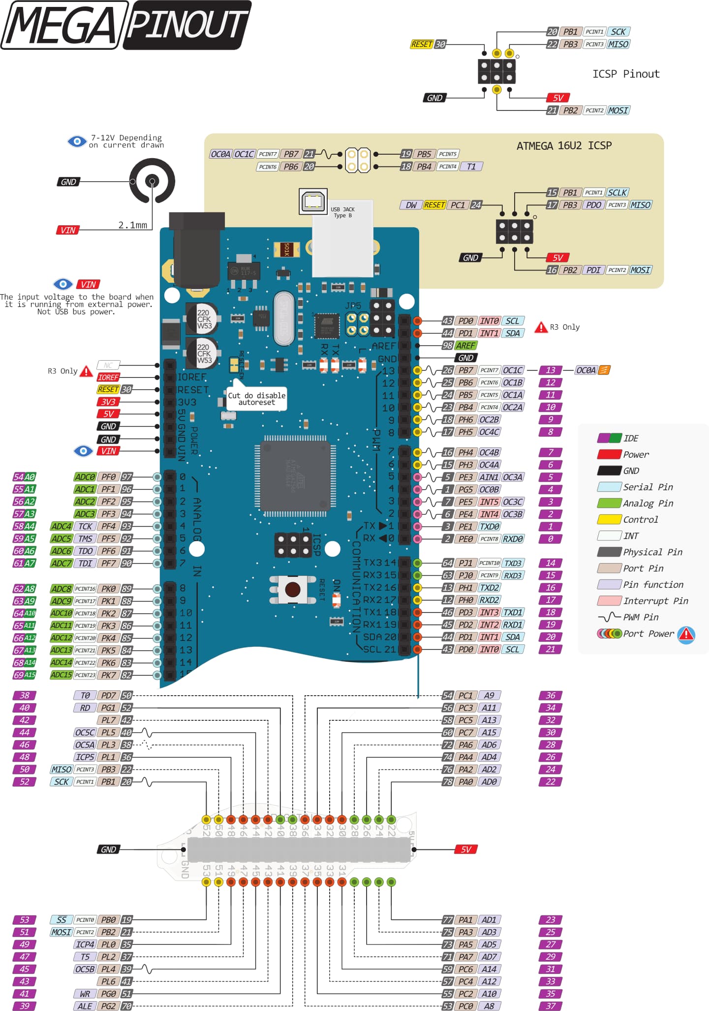
This image shows the pins for your MEGA2560... you want one PWM pin per motor to change motor speeds... look for the "tilde/squigly" lines labeled "control" representing PWM pins.
My motor controller L293D DC Motor Driver is the Adriano Motor Shield R3 I can see the layout for motor driver the pins have to be applied to the pin lay for the shield. I’m working on the motor control with the sketch. Working with larger board is better not as much fine small wiring for solder job. Saves the eyes. The power is feed directly to the motors external feed goes to board. The connections on the back four are unconnected. Vin/break/sns1/sns0 2152403.pdf (167.1 KB)
I do not understand the meaning of what you have written. Do you have a question? Do you have a wiring problem? Also, would you write in your language and use Translate and copy/paste the English translation here?
Function Channel A Channel B
Direction Digital 12 Digital 13
Speed (PWM) Digital 3 Digital 11
Brake Digital 9 Digital 8
Current Sensing Analog 0 Analog 1
Ok new subject what do you think if I tried to incorporate Adriano Mega ATmega2560 to LoRa instead of wifi? This could be ne can of worms and could you help?
Arduino Mega ATmega2560 to LoRa SX1278 Ra-02 Ai Thinker