on the official Arduino Page there is a guide explaining how to put a fully working Arduino onto a breadboard.
Link: http://arduino.cc/en/Main/Standalone
I followed all the steps there with one difference. Instead of this "USB to Serial breakout board" from Adafruit
I used this one
because it is much smaller and could be integrated in my final product more easily.
In the guide, the author uses four pins only to connect the "USB to serial breakout board" to the ATMEGA:
Sice the 4 pins that are used (VCC, GND, RX, TX) are available on my smaller "USB to serial breakout board" it is no problem to connect the two. There is only one problem. Whenever I upload a program to the ATMEGA, I have to press the reset button manually. This is anoying, because there is only a small time window for pressing it. And I have have to upload frequently during the software development steps.
The obvious solution would be to let the "USB to serial breakout board" automatically reset the ATMEGA when the upload starts. I found the following guide on how to allow for this automatic reset here: Arduino programmer on breadboard using FT232RL - BuildCircuit.COM.
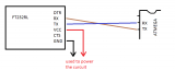
It seems that my "USB to serial breakout board" needs the pins RTS and DTR but it only has CTS and DTR. Is it possible to get automatic resetting with the CTS instead of RTS?
thank you very much for your fast reply. Your solution sounds very simple.
Just to be sure, I added an adjusted circuit. I would be very happy, if you could have a quick look, if it is correct:
Compared to this circuit,
I only left out the 100 Ohm resistor (or is 100R = 100 kilo Ohm?). Do you know what this resistor would be good for and why I can leave it out?
I think it is unnecesary to connect your usb breakout rst to arduino's rst, thus the resistor and the connection is unnecesary. Only DTR matters for auto-reset feature.
100R is 100 ohm.
100K is 100 Kohm.
A 10K pullup from Reset to +5 is needed to "recharge" the 0.1uF cap after the DTR signal discharges it to create the reset pulse.
That connection is right (place it as close as possible).
MegaMatze2:
Isn't that enough?
One would think that is enough, but between that cap and the breakout board there's an electric trace which may be interferred by electronic noise. That's why it is recommended to place a decoupling cap for each IC supply and to place it as close as possible to it.
In other words, place a cap at the beginning and at the end of the road.
So I have to place such a "noise reduction" capacitor next to the 7805 power regulator, the atmega and the usb2serial. Where "next to" really means as close as possible.
I have the new final circuit in the picture below. Note that I rewired the red wire right of the atmega, to have its two +5V connections "more close" to a capacitor. There are 3 of the 0.1 uF capacitor now.
with
By the way, does it make any difference, whether I use ceramic capacitor for the 0.1 uF or Electrolytic capacitor?
In fact I have one ceramic and two Electrolytic .
MegaMatze2:
By the way, does it make any difference, whether I use ceramic capacitor for the 0.1 uF or Electrolytic capacitor?
In fact I have one ceramic and two Electrolytic .
I've read electrolytic do have higher failure rates, other than that I wouldn't know.