I'm about to purchase the arduino beetle as it will take up less space on my bread board of my project, and it means I can get back to programming my uno as per my starter kit
I can see that there are no pins on it however. Is there a solderless way to secure it on my breadboard with pins, as well as connect the contacts to the jumper wires.
Thank you. Would you be able to point in the direction of where to find these pins? I can't tell from the beetle product description if there's a particular size, and all the ones I find come in blocks of over four pins and don't appear to be able to be broken up in to smaller pieces.
The closest I've found are these:
Please post a link to the electromagnet. The driver controls the large current usually required, and it MUST have inductive kick protection, or the circuit will be destroyed.
Breadboard tracks should not be expected to conduct much more than about 100 mA current, and output pins should not be expected to provide more than 20 mA.
It is the 6v version of this energise to release electromagnet:
It just says 6V/3.4W. An online calculator tells me that means that the current is 566.666667mA. Is that correct?
If that is the case, does that mean that the electromagnet pulls 566mA, which would damage either the bread board or the pins on the arduino? In which case I would need a driver in between the electromagnet and the rest of the circuit? Or does the driver have a switching mechanism?
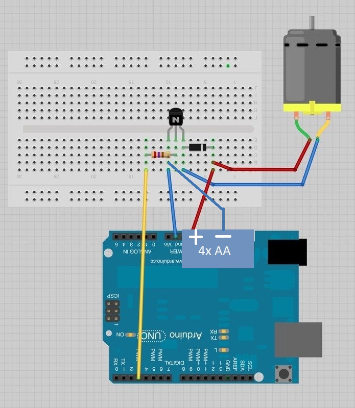
So far I've used this layout (but with an electromagnet instead of a motor):
In the circuit you linked, the transistor is the driver. However, in that circuit, Adafruit makes the common but terrible recommendation to power the motor from the Arduino 5V outlet. Don't do that as it can damage the Arduino (of course Adafruit will be happy to sell you another).
For any motor or coil, the diode is absolutely required.
To power your solenoid, use either a 5V phone charger or 4xAA battery pack. Don't forget to connect the grounds.
I'm a bit confused as to how to connect it and ground everything. In the adafruit diagram, the 5v goes from the ardunio on to the breadboard connecting to both the diode and the motor.
But if I replace the 5v pin with the AA batteries then the tracks will still burn as the current will be too high.
So would the attached diagram (soldered on pcb instead of breadboard) be correct? I've basically just replaced the 5V and gnd pins on the arduino with those of the battery pack.
Or does the gnd pin on the arduino need to also be used?
jremington:
In the circuit you linked, the transistor is the driver. However, in that circuit, Adafruit makes the common but terrible recommendation to power the motor from the Arduino 5V outlet. Don't do that as it can damage the Arduino (of course Adafruit will be happy to sell you another).
Albeit they do explain:
The motor that comes with Adafruit Arduino kits does not draw more than 250mA but if you have a different motor, it could easily draw 1000mA, more than a USB port can handle! If you aren't sure of a motor's current draw, power the Arduino from a wall adapter, not just USB
Which is of course, still nonsense, as it is not the Arduino you wish to power, but the motor or solenoid, and if you interpreted this as advice to power the Arduino from the "barrel jack" or "Vin", that is even more useless!
Well, now you are missing a connection from the ground of the battery/ power supply to the Arduino ground. At least the original diagram had that implicitly.
Got it working However, when I switch on the trinket it appears to malfunction. Just the solid green light and faint solid red light. It is not recognised by my PC.
If I unplug it from my PCB board and then switch it on it is OK. The red light flashes as usual as it boots. Then if I plug back in to the PCB board (keeping it switched on), it behaves fine.
I believe this was only a problem once I'd soldered in the resistor, transistor and diode.
I have attached my work.
Short of starting again is there anything I can try to resolve?
Update: I resolved by resoldering the L that goes from D to 6 :))