I want to control a MOSFET with Arduino UNO using the PWM signal. The thing is the MOSFET that I want to use require a rated gate threshold voltage that is higher of what the Arduino UNO can support, which is imposing the need of using a driver circuit to amplify the PWM signal comming from Arduino.
Is there a way to amplify the Arduino PWM signal (Tutorial of a driver circuit to control MOSFETs that have a higher rated gate threshold voltage of Arduino's PWM signal)
You can use a gate-driver IC such as IR4427, or you can build your own push-pull using transistors for small signals.
If the PWM has a low frequency, you can just use a level shifter (one transistor) instead of push-pull.
What is the frequency of the PWM signal?
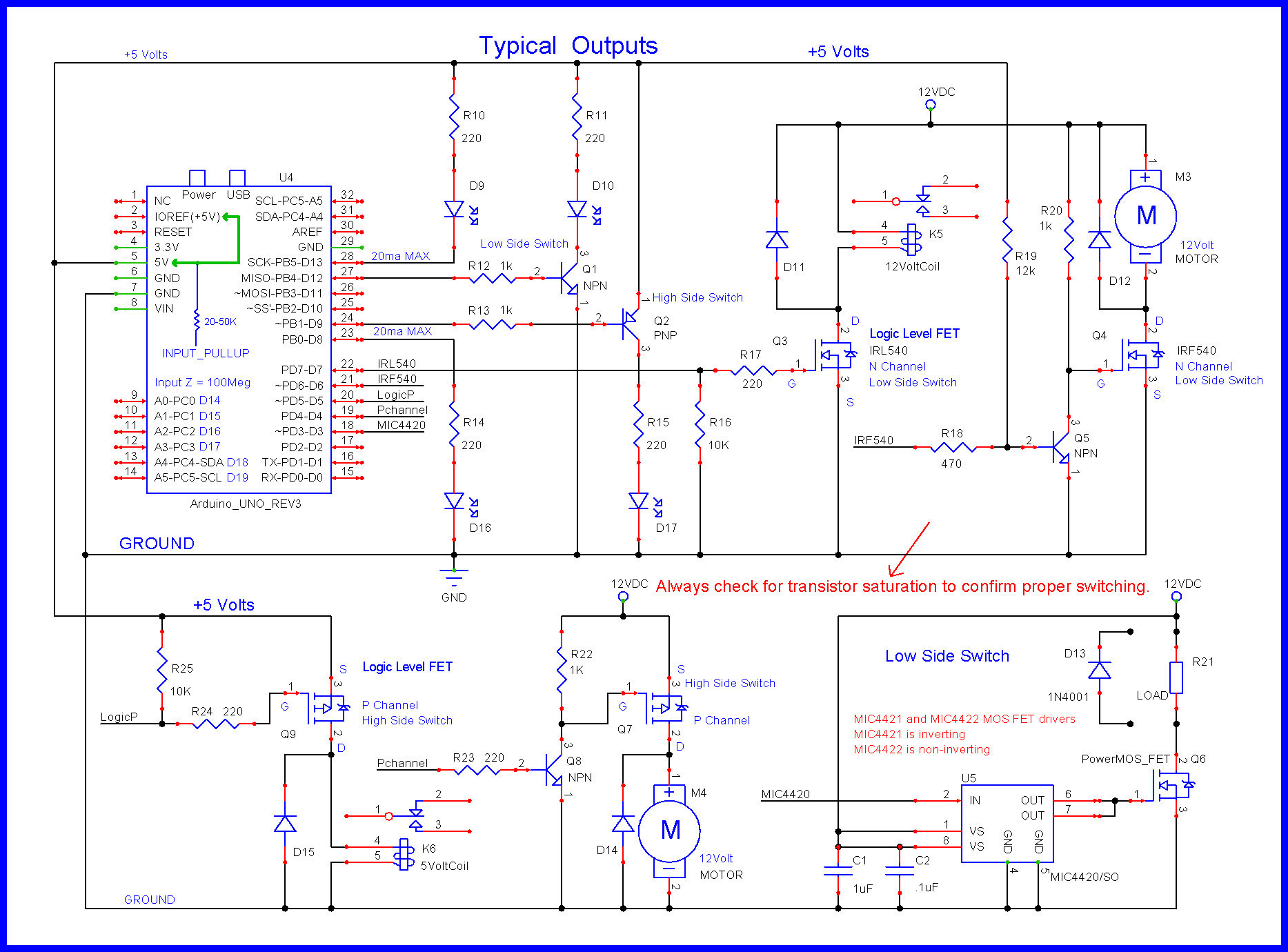
You need a gate-driver chip, powered from 12V, to drive a large MOSFET like that. For instance a MIC4422 will do it (and the last time I checked is available in DIP8, not just in surface-mount).
That MOSFET has 11nF of gate capacitance, and is high voltage with significant drain-gate capacitance too - this pretty much mandates a strong gate driver like this.
BTW the threshold voltage is irrelevant for using a MOSFET as a switch, the important figure is the voltage quoted for Rds(on) - for this MOSFET its 10V, which means a minimum of 10V is needed to switch it on properly (which means 12V is typically used).
I don't have any preference on the frequency. I'm planing on using the default Arduino PWM signal ( (490 or 980 Hz).
Do you have by any chance a tutorial or circuit schema on how to use this gate-driver IC with Arduino?
Do you have by any chance a tutorial or circuit schema on how to use this gate-driver with Arduino? I'm new to whole thing and I want to make sure that I'm doing this the right way.
Regarding the first picture, is there a specific capacitor type that I should use ? (Aluminium Capacitors - Tantalum Capacitors - Polyester Film Capacitors - ....) or can I use any type that I want?
the PWM signal coming from Arduino should be injected in the red arrow showed in the picture, right?
It is like this.
The circuit GND must be shared with Arduino.
If only one MOSFET is required and B-ch is not required, there is no problem with B-ch both input and output not connected.
Also, if with the PWM frequency from 500Hz to 1kHz, there is a possibility that there is no problem just by level shifter with a transistor for small signals and pull-up resistor of about 1K ohm.
Thank you for your reply.
I have a question though : for the selection criteria, is there a type of resistor should I use ? (carbon film resistor - metalic film resistor - ..) .
Same question for the capacitor
(Multi layer) Ceramic capacitor for 0.1uF
Multi layer ceramic capacitor or Electrolytic capacitor for 4.7uF
Any cheap resistor (probably Carbon film resistor) for all resistors.