I hae an arduino, some fets and ABB soft starter. Soft starter works with 24 VDC and I wouldl ike have my arduino to give a starting signal.
So I was wondering how to connect the FET since all the example pics of FET switch have a load on the high side of it and it controls the connection to ground. But to get the motor started with soft start it wants 24 VDC to A1 and ST and as long as it has the power the motor will stay running.
Should I just consider the ST as the ground or what?
Now, the actual implementation will have a lot to do with how much current is needed at the ST input. So, hard to supply details until you reveal more information [as requested by MarkT]. Include what Arduino you plan to use [or at least whether it's a 3.3V or 5V]. Ask specific questions if you need further help.
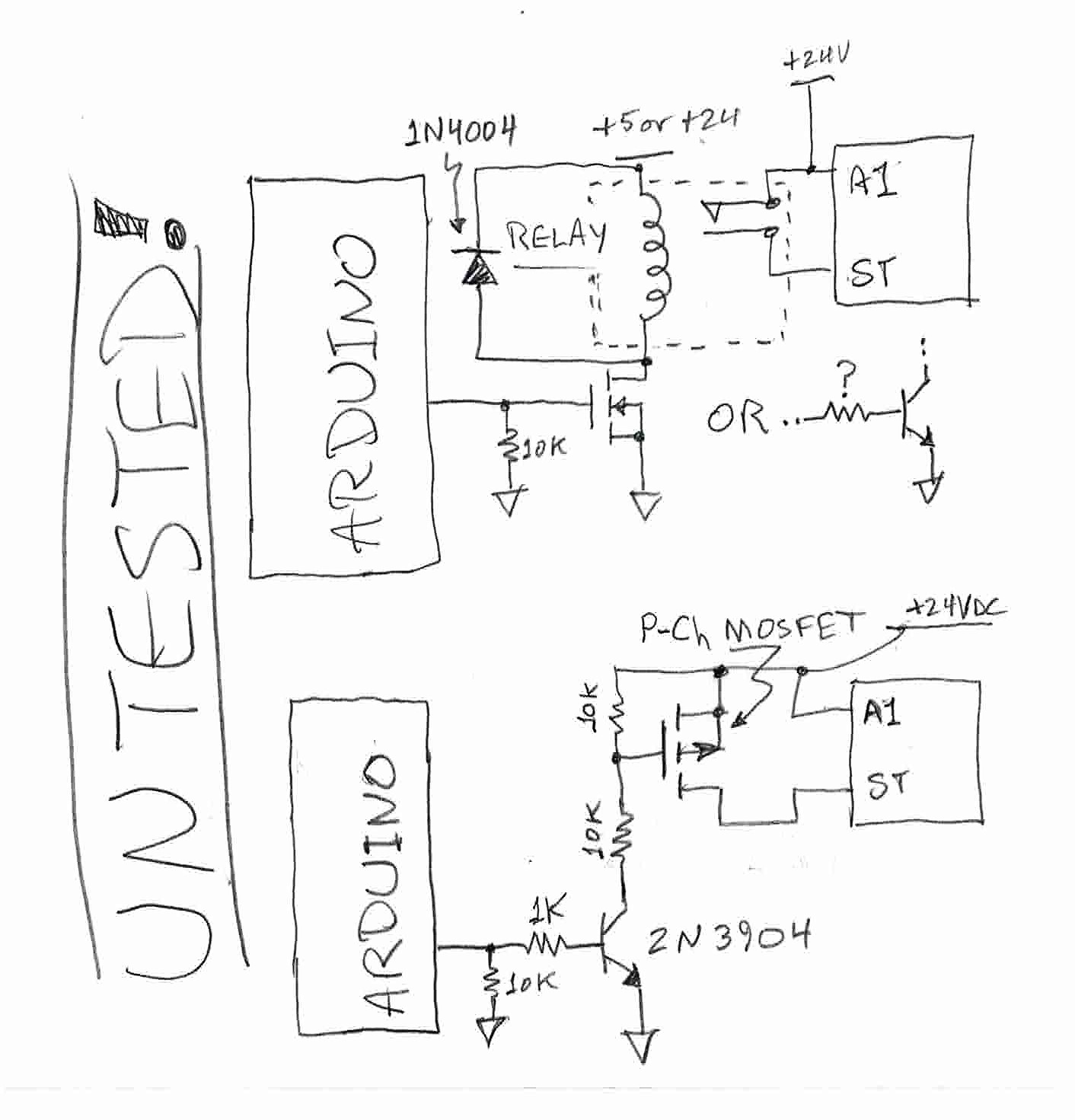
The N-channel MOSFET [the one connected directly to an Arduino output] must be a Logic Level device -- and if this is a 3.3V Arduino, then it needs to be able to turn fully on [go into saturation], with a minimum of 3V at the Gate. The P-Channel MOSFET doesn't need to be Logic Level.
Note: If the input capacitance, on the N-Channel MOSFET [the one connected directly to an Arduino output], is greater than around 300pF, then I suggest adding a series resistor from the Arduino output, to the MOSFET Gate [on the MOSFET side of the 10k resistor--like is shown in the Bipolar Transistor equivalent circuit]. OR, let's just say, if the MOSFET has a ID continuous rating of 1A or more, then add the series resistor. OR, just throw a 170Ω resistor in series with the Gate [on the MOSFET side of the 10k resistor], for good measure.
The zener makes sure the voltage from the Gate to Source never exceeds around 12V [use a P-channel MOSFET with a MAX Gate Voltage rating greater than 12V [more like 16V or more]. It also applies a low equivalent resistance so the BiPolar Transistor can charge the Gate capacitance more quickly [thus more rapid switching].
Also, that 1k resistor, on the base of that 2N3904, can be more like 25k. Since the Collector current will be, max, around 1.2mA. Using a Beta of 10 to insure the 2N3904 switches quickly and is well saturated: IB = IC/10 = 120uA
This page has a much better drive circuit for 24volt high-side switching.
The 2N3904 is used as a current source, and the zener is across source/gate, where it should be.
Leo..
Wawa: This page has a much better drive circuit for 24volt high-side switching.
The 2N3904 is used as a current source, and the zener is across source/gate, where it should be.
Leo..
This switches between off (base high, zener limits gate voltage to 12V) and broken (base low, zener connected to nonconductive BJT, gate voltage not limited, so 24V), doesn't it?
ElCaron:
This switches between off (base high, zener limits gate voltage to 12V) and broken (base low, zener connected to nonconductive BJT, gate voltage not limited, so 24V), doesn't it?
No. Actually, when the BJT is open, the 10k resistor pulls the Gate up to 24V and thus, there is zero volts from the Gate-to-Source. This happens because the open BJT behaves like a very large resistance, which, in series with the 10k resistor behaves like a voltage divider, and because 10k is a very low resistance compared to the effective resistance across BJT [Collector-Emitter], all of the voltage is dropped across the BJT [and the zener, which, actually, will have very little voltage across it, because of the extremely low current].
It's so hard to find relevant information on anything since people want you to buy the official parts and controllers, not make your own, so they withhold information or outright lie sometimes...
That's a catalogue, and it only mentions PSR30-600-70 and PSR30-600-81, not the PSR30-600-11, for
which you need the datasheet to find out the relevant connections and ratings.
It's so hard to find relevant information on anything since people want you to buy the official parts and controllers, not make your own, so they withhold information or outright lie sometimes...
Huh? The soft-starter info is all over the web. The manufacturer and distributors have it posted. The links in the product document work for me. Here is a direct link to the instruction sheet on the ABB server:
The ST (start) input requires a maintained +24 vdc level to run the motor. The soft-start also requires overcurrent protection in the form of fuses or a manual motor starter (MS325) with integrated magnetic breaker.
avr_fred:
Huh? The soft-starter info is all over the web. The manufacturer and distributors have it posted. The links in the product document work for me. Here is a direct link to the instruction sheet on the ABB server:
Its a family of many variants - the variant 30-600-11 isn't mentioned anywhere in these documents. It may
be an older model and be different for the details of its I/O - certainly some of the PSR30-600 series are
described as AC control. I prefer to work from the correct documentation if I don't have the thing in front of me.