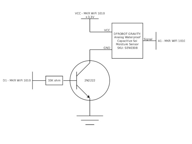
I am using a DFROBOT Gravity: Analog Waterproof Capacitive Soil Moisture Sensor (SKU: SEN0308) with an Arduino MKR WiFi 1010.
I use a transistor to restrict the sensor current when it's not being used because the application runs on battery and I want to conserve power.
This is the circuit diagram:
Reading the sensor involves
setup()
{
	pinMode(1, OUTPUT);
	pinMode(A1, INPUT);

	digitalWrite(1, LOW);
}

loop()
{
	digitalWrite(1, HIGH);

	delay(2000);

	int sensor_value = analogRead(A1);

	digitalWrite(1, LOW );

	/* ... do stuff, then ... */
	LowPower.sleep(ONEHOUR);
}
The application is working properly.
When the MCU Digital Output 1 drives the transistor base HIGH, my multimeter shows that the voltage on the "Signal" wire connected to the MCU's Analog Input 1 (A1) varies as the specified by the manufacturer in the range of 0-3V. This is well within the specification for the MKR WiFi 1010.
My concern is that when the MCU Digital Output 1 pulls the transistor base LOW, blocking current through the transistor and turning off the sensor, my multimeter shows that the voltage on the "Signal" wire connected to the MCU's Analog Input 1 (A1) rises to around 3.7V.
I think that this exceeds the specified voltage input to the MCU.
Your topic has been moved to a more suitable location on the forum. Installation and Troubleshooting is not for problems with (nor for advice on) your project See About the Installation & Troubleshooting category.
With no current limiting resistor when you turn the transistor on, the current out the pin Arduino pin is too much and will damage it and possibly the transistor as well. Looks like it has already been damaged, which is why you are seeing this excess voltage on the pin.
But check the transistor's connections are the correct way round as well.
That circuit is not usable for your purpose. If you lack fundamental transistor circuit knowledge then you should get and strictly follow a high-side switch circuit diagram or ready made module. That circuit type has been discussed in the forum many times.
Thank you for your advice. I appreciate it very much.
Searching for "high side circuit diagram" yields more than 50 threads. Reading through several has not yielded much that was applicable to this situation, which is all low voltage and low current.
Would you please give me a pointer to one or more threads on the forum or another resource that provides more detail on "a high side circuit diagram" that would be appropriate for this use?
I am also open to using a "ready made module." Would you please suggest one or more examples of specific "modules" that illustrate the kind of devices that are suited to this project?
The parameters are
Supply voltage is 5V
Enable/Disable signal voltage from Arduino is 3.3V
Sensor device will work with Supply from 3V to 5V
Sensor device draws less than 10 mA when connected to 5V source
Gentlemen, thank you for the kind and gracious help.
Suppose, instead of using a high-side solution, I leave the low-side
transitor in place to restrict the current and simply change the high-side
supply voltage to a level that is safe for the MCU's analog input?
The MCU has a 3.3V output capable of supplying 600 mA. That should be
sufficient for the sensor and safe for the analog input.
If you don't think that this is wise, I'll follow the directions to build the high side circuit.
So... I'm learning. I may finally understand why the strong recommendations for using a high side solution. Please correct me if I'm wrong.
I tried the low side circuit on the breadboard and it works perfectly, the current is managed and the analog input is safe.
The only problem is that the data from the sensor is junk. HA!
I think the sensor wants ground to be ground, real ground. With the transistor in between the sensor and the ground, the results are completely unreliable. If I bypass the transistor, the results are pristine.
So, high-side switch here we come.
My father used to say that "the school of hard knocks is a tough school but some fools will learn in no other." I'm getting "schooled!" HA!
Thank you for the tip about "time after power on" delays. I tested that and didn't see anything significant but, nonetheless, I inserted a 2 second delay for simple peace of mind.
Another issue that occurred to me is that, with VCC at 3.3V and the transistor causing a 0.7V voltage drop, the sensor is getting on 2.6V. Right? If so, then that's below the voltage spec on the sensor, which is 3.3V to 5.5V. That could be the issue rather than the grounding issue.
Please help me understand the high side solution. As I understand it, transistors are current-limiting devices not voltage limiting devices. I understand when "the switch is open," the high side switch will prevent current from flowing into the sensor. So, does it act like a "high value" resistor, with a correspondingly high voltage drop, so that the voltage at the sensor is also reduced?
I know this is a truly basic question but that's where I am. A pointer to a tutorial would be sufficient...
No. The CE voltage drop is less than 0.4V. Also I laid out the circuit for a 5V supply:
I think that you confuse common emitter and common collector transistor circuits. The PNP transistor works like the NPN in your first attempt, only with + and - lines exchanged. 5V-0.4V=4.6V for the sensor.
If you want to power both the controller and sensor by the same voltage then you can either power the sensor by a GPIO pin - if the pin provides enough current - or directly by a P channel logic MOSFET.
First, thanks again to those who replied so patiently to my naive questions. I learned a lot.
Second, in reflecting on what became the fundamental issue in this discussion, i.e. wanting to reduce average power consumption, it occurred to me that I could save even more power by shutting down power to both the MCU and the sensor when the system is intended to be idle. All I would need is a low power timer and high side switch in front of the MCU.
As usual, once I had a clear idea of what I needed, I found that it's a common requirement and that someone makes a device that does this far more efficiently than I ever could:
This device allows the MCU to signal when it's ready to be powered down and will restore power sometime later. It's very simple and consumes only a few nano-amps.
Adafruit sells a breakout board for a few bucks that puts it all together.
Having the system powered off "most of the time" pushes the average power consumption of the system down so far that it obviates the need to be "clever" about the rest of the power management strategy.