I got one of these Yellow/Blue Keyes OLEDs the other day and had exactly the same snow display.
Googled around for any information and it turns out that there's a problem with the design of the display - there's no reset. Although it doesn't have a reset connection, unlike other makes (such as Heltec) it won't even allow a reset. Pin 14 (on the display ribbon connection) is permanently connected to VCC. However, in order to create a reset, pin 14 needs to temporarily be connected to GND, which is impossible the way that the board is set up.
Other 4-pin OLEDs get around this by creating a reset pulse when the OLED is switched on. The usual method is by connecting pin 14 to VCC (or a 3v3 supply from an on-board regulator) via a 10k resistor and also connecting pin 14 to GND via a 100n cap. This is the arrangement that Heltec uses.
There are a few ways mentioned about what can be done to cure the problem, but none of the non-invasive ones, such as using a LED or 100R resistor in series with VCC worked for me. Other options included what seemed to be a bit of messing about, such as temporarily shorting pin 14/R3 to GND which I didn't try as I wanted a permanent solution. Another option (if I remember correctly) involves soldering a wire onto R4/pin 14 and connecting that to the Arduino as a reset wire and adding code into the Arduino program. As that would effectively short out VCC to GND, I wasn't going to bother to try that either.
As I saw it, the solution was simply to add the pulse circuit to pin 14 and then the Keyes OLED would work like the Haltec one. I finally got round to doing it this afternoon. It's an easy enough job, but it does involve some fine soldering work (not much) and good eyesight 
Brief circuit description
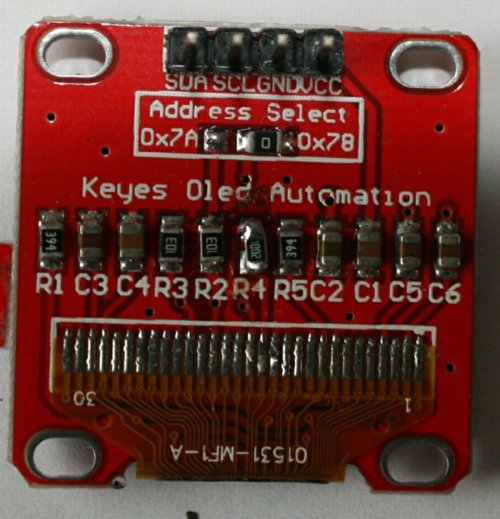
Ribbon cable pin 14 connects to R4 which connects to VCC. R4 is in fact just a link (these are sometimes labelled as 0 or 0R and are often known as 0R resistors). This means that pin 14 is going directly to VCC through R4.
Doing it
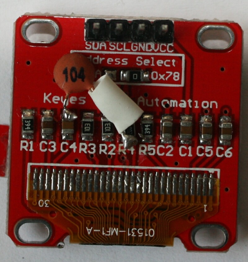
The simplest solution is to replace R4 with a 10k resistor. R4 is surface mounted (SMD) and is a size 0805. Luckily I had some 10k 0805 SMDs and I just removed the existing R4 (I found it easier to gently snap the resistor in 2 with a pair of side cutters and then unsolder each end) and replaced it with the 10k. That was half the job done!. The second half was fitting the capacitor. One end of the capacitor needed to be soldered to the pin 14 side of R4 and the other end to GND.
There were two handy GND points I could use - pins 15 and 16 both connect to GND and so I could have soldered one end of the capacitor to there. If I had a 1206 size 100nF capacitor I might have been tempted, but as I didn't and was using a capacitor with legs on, I decided to connect it to the far end of either R1, C3 or C4. This also has the advantage that it avoided any risk of occidentally creating solder bridges across other terminals on the ribbon cable.
I used a 100nF ceramic disc capacitor. I trimmed one leg very short and soldered this to the far end of C4. I trimmed a bit off the other leg, slid on a piece of sleeving (to prevent the bare leg shorting against any other component) and soldered the leg to the far end of R4. I checked the work to make sure there were no shorts anywhere, then connected the OLED up to the Arduino. Snow! However, after a few seconds the snow disappeared and was replaced by Hello World. Success!. I think the initial few seconds delay was due to the pulse kicking in. Subsequent turning on and off brought the normal display up instantly. Therefore, it seems that it only needs to be reset occasionally, even though it will be reset every time it is switched on.
The connections to the Arduino were the standard ones - 5 for SDL, 4 for SDA plus 5v and GND.
Library used - U8glib
constructor call:
U8GLIB_SSD1306_128X64 u8g(U8G_I2C_OPT_NONE|U8G_I2C_OPT_DEV_0); // I2C / TWI
The OLED address remained the default 0x78. I've left the OLED running for the past six hours and all is OK. It also seems to work OK on 3v3 from the Arduino, so I might use that when I can.
I've attached some before and after photos of the OLED showing the alterations. It's not as tidy as I'd like it, but at least it works
Edit
I've noticed that, because of the sleeving on the capacitor lead, the photo doesn't show clearly where it connects to on R4. See the newly added CapConnections photo for clarification.
PS - more information on this problem here (also see the links on that page):
http://forum.arduino.cc/index.php?topic=317289.0