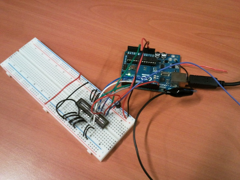
Attached some pics that should get you going before it arrives. Had to use the phone because someone borrowed my serial interface for the scope.
The first one shows the setup: no pull-ups and long wires. Notice that I connect DOS to the Aref of the arduino.
The second one is some data. It's 4 pics combined because I'm only allowed to upload 4 attachments here.
When the sensor is fully exposed to light the levels are not equal, they're one of 2 values. The odd ones are always the same, the even ones are always the same. This is because the chip uses 2 shift registers to push analog data out, these 2 registers are connected to odd or even CCD elements and they're not 100% identical. The minimum voltage is ~1.5V DC, when the sensor is saturated with light
This is with the sensor completely covered with a box, minimum light. Max voltage ~3.0V
I placed 2 cut pieces of ribbon cable on the sensor. The first one overlaps with S1, the second one is somewhere at 2/3
Long exposure over t, I marked the location of S1 (yellow arrow) to show the start. The blue circles show shadow cast by the 3 wires that hang over the sensor. This is with a box with a slit over the setup.
I modified the code somewhat to check for a level at 2.1V (with DOS at ARef). It stores a bit for each pixel in a 256 byte buffer. That buffer is sent to serial (115200bps, 8N1, no handshake) once every second. 0 = dark, 1 = light 1 = dark, 0 = light
There's loop unfolding to avoid a 16-bit variable in the main loop. Everything compiles to 1230 bytes.
Compile in AVRStudio with compiler optimisation -O1. If you compile with -O0 you'll get wider timings but a chunk of code of ~4Kb.
thanks for the code. I have installed AVRStudio but not used it yet. I am using the arduino IDE to compile. So I will first try to identify the difference between your code and my approach (as I want to learn and understand)
I'll keep you posted on the progress
Ciao, Mathias
Let me know if you encounter problems. I'll be updating on a different website next week with optimized code, I posted here because there's too little info on these sensors for hobbyists and they're really great devices. And you were so close
Salut Fred,
I have not yet spotted the difference between your timing and mine ... However, I must admit, that I do not understand how you read the value that is stored in the data array. It looks to me like you are only storing a on/off infomation bit per pixel ... (please excuse my poor C skills but I reactivated my knowledge only a year ago and learned C in 1987)
Can you show the link to the other forum you mentioned? Would be interesting to see more info on these devices
I read the adc value (redefined as OS at the top of the file) and check the level. I deduce 1 bit per pixel from this (above or below a given threshold) and store that in a 2048 bit array.
What you do with the individual values is up to you, in my case I just need light/dark info with respect to a level - my implementation only needs one bit per pixel.
I haven't looked at your code, sorry I don't know how you process the data.
I haven't yet finished my code, I'll only upload it once it's up to my standards. Tomorrow I have the hole day to work on it so fingers crossed
BTW, I don't mean to lure you away from the arduino IDE but for timing-critical implementations it's good to have an IDE where you're in full control.
Salut Fred,
due to the Chinese New Year, the delivery of the scope takes a bit longer. So I gave Atmel Studio a try, installed it and loaded your code.
I can see why you prefer the Atmel Studio, as it provides the experienced programmer with more flexibility, but is sometimes quite cumbersome: i.e. I have to declare a external command for each port I have an arduino connected. I will continue to use both where the advantages of one come handy.
I loaded a demo code and it worked fine (there is a wonderful tutorial at http://www.jayconsystems.com/tutorial/atmerpt1/).
Then I loaded the SerialCCD code you provided but the output is nothing but F´s - all pixel seem to be set. I then looked at the code where you read the ADC and I do not understand the while condition. I would have expected to see a
while (ADCSRA & (1<<ADSC));
instead of the while(!(ADCSRA & (1 << ADIF))); ADCSRA |= (1 << ADIF);
If I connect the A0 input with GND, I still get all pixel reported as ones, which indicates that the ADC read is not correct.
As you have tested the code, I am now completely puzzled ...
I attached the wiring
Hello, i'm working on TCD1201D and i read all posts. At moment i'm stopped by a insurmountable problem :
After many test i optmized (deleted/restricted delay, serial print etc.) the fw developped by GastonLagaffe but the behavior of CCD is alway the same, the timing seems ok (in effect BT,RS,... signals are correct), but the value of video-out is always relative to first pixel.
To test this i put a piece of paper to cover CCD window, but if i start by side of PIN1 toward PIN11 at PIN1 i found "dark" values (same value to other pixel), viceversa if i cover CCD starting from PIN11 toward PIN1 at PIN1 i read "light" values up to witch the first pixel are blinded.
Then i suppose that i don't be able to shift out all values and i read only the first value....
Can Anyone help me?
i'm having your same problem, so i've tried to write again the code, verifying the data with the datasheet.
Seems like the only difference is while we wait the inital 2ms for SH, we should still send RS and BT cicle, even if we don't change the clock.
i've asked a friend to screen some oscilloscope reading for me, but if you want to help me you can do it, as i don't know when he will find a bit of time for that.
actually, the first pixel to be read seems to stick for a lot of measure, and came from the first DUMMY pixel read:
after some testing, i see really strange behaviur!!
seems like i'm reading only the LAST hundred or so points, therest are all saturated or similar, they just are 0.
i see that "last" value coming from fisrt 32 pixex, some of the "normal" pixel, and then again on the last 14 dirty pixel!
seems like the first 14 byte of the 32 are repeated again at the end. weird!
i'm posting code used in arduino and processing, and a couple of screen: with last pixel covedered, and witrh screen off (almost no light in the room, just some led)
black pixel = 0
white pixel = 255
yellow pixel = not mapped, here just to fill graphically the grid
please not i'm using a byte array as buffer, but because arduino UNO does NOT have 2k of ram, i'm only saving HALF reading:
for (int i=0; i<1024;i++){
    sdacCounter++;
    read1Low();
    read1High();
  }
as you can see, the read1High() is going to replace the read on low, as the index on the writing array is "sdacCounter". So if you have a MEGA (or you write to faster bus or... whatever) you can increse the array and then do
for (int i=0; i<1024;i++){
    sdacCounter++;
    read1Low();
    sdacCounter++;
    read1High();
  }
aslo please note last bit cannot be trusted as it is overrided by the last of the 14 dummy pixel. who care?
the ino is the code to upload to arduino UNO (with connection and souch), the pde is the visualizer from processing (see the video TCD1201D with arduino + processing test 2 - YouTube) and finally a visual help for making connection. Those are what i'm preparing to write an article about this sensor, if i'll find some time!
I tried this code but seems the problem remains
maybe its because I'm using arduino pro mini since it has 1k of sram
could this cause the error?
and what should I do to fix this?