I want to build an LM298 based motor driver and I was wondering what parts I should order to get started. I'm going to drive small DC motors.
Thanks.
I want to build an LM298 based motor driver and I was wondering what parts I should order to get started. I'm going to drive small DC motors.
Thanks.
This depends on what features you want to implement. Google lm298 circuit and lots comes up.
You can order a kit, or look into BOM (parts list):
https://www.sparkfun.com/products/9670
Thanks! Looks like this one fits the bill: http://content.solarbotics.com/products/schematics/solarbotics-l298_schematic_complete.jpg
I just ordered a couple of L298N's and a bunch of diodes.
Looks like I can build a little motor driver pretty cheap!
If this part is so popular, why does no one stock it?
Is it considered a specialty part?
Search L298. I don't know what the differences in an "L" and "LM" are but it seems as if an "L" will work as a small low amp driver for little hobby motors.
Maybe someone else will chime in.
hoff70:
Search L298. I don't know what the differences in an "L" and "LM" are but it seems as if an "L" will work as a small low amp driver for little hobby motors.Maybe someone else will chime in.
Thanks. Now that I look at it more closely, I think that L298 is the part number. The OP may have typed LM298 in error out of force of habit because of LM being on such a huge number of parts.
The difference between L and LM is purely in what the manufacturers assigned
as the P/Ns, so you need to use the correct one. There are quite a few h-bridges
with the L nomenclature. L298, L293D are quite popular.
http://www.jameco.com/webapp/wcs/stores/servlet/Product_10001_10001_245403_-1
There are 2 'drivers used, the 16 pin dip L293 and the Multiwatt package L298 the L293 can be used for really small motors and the L298 can be used for medium power motors, The 298 requires a heatsink and the lack of a heatsinkable package makes the 293 limited in power dissipation. Although driver transistors can be added for more power. A nice L298 shield is sold by Pololu and there are several others that stock or sell similar types.
The IC can be purchased from several sources including Dipmicro who sell the chip for $3.25 and a shield for an Arduino for $11.95. Dipmicro is useful as they have prices nearly as good as china, ship quickly (from Canada) and sell a lot of Arduino stuff not too high priced either...
The L298 is a 2A 46V device, the L2993 is a 36V 660 ma to 1A device with and W/O diodes and current sense B, D, E (20 pin W current sense)... WWW.dipmicro.com
Doc
I'd avoid both the L298 and L293 series, there are bipolar devices with darlington outputs, and as a result they have a large voltage drop (which can be as high as 3V) and run very hot. Use a motor driver with mosfet outputs instead, such as the MC33926. Pololu makes a nice breakout board for it, see http://www.pololu.com/catalog/product/1212.
Thank you Sir for that neat link. Last time I used those decicees I used the L293 to control an H bridge... Didn't want to but there was a need for a much larger motor and reworking the rest of the control network was out of the question. I did have to change out the Brake resistor though.
Doc
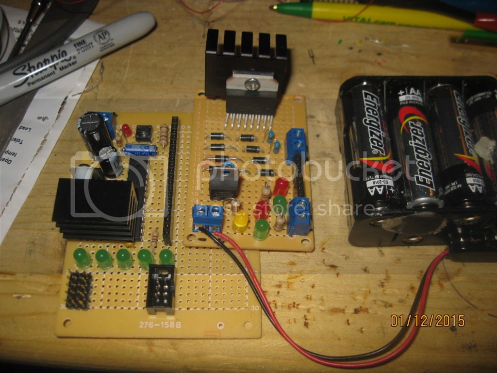
Thanks for all the input! I got my parts in and built this:
It's basically this: http://www.solarbotics.com/product/k_cmd/
Schematic: http://content.solarbotics.com/products/schematics/solarbotics-l298_schematic_complete.jpg
I'm a little confused about the 7805 though. Does the 5V from the regulator go to the pin marked 5V on the chip? There is no trace on the schematic to it.
Plus any advise on making this thing work with my Arduino would be most welcome!
Yes, pin 9 of the L298N should go to the +5v output from the regulator. Alternatively, connect pin 9 to the +5v supply of the Arduino that your board is connected to, then the regulator is redundant.
PS - you should also have a capacitor of several 100s or 1000s of uF connected between pin 4 (+) and the ground pins (-) of the L298N.
If you google for "Arduino l298n" you will finds lots of matches.
Thanks. I implemented the changes you recommended. One thing I noticed was that one of the leds wired to the motor lugs illuminated once I hooked the 5V from the regulator up.
I loaded a sketch and got some blinky action but I think I'm confused about interfacing the Arduino with the controller. The controller has these inputs from the Arduino:
L1
L2
E 1-2
L3
L4
E 3-4
The sketch I'm fooling with has these outputs:
const int pwmA = 3;
const int pwmB = 11;
const int brakeA = 9;
const int brakeB = 8;
const int dirA = 12;
const int dirB = 13;
I'm doing some searching...
hoff70:
Thanks. I implemented the changes you recommended. One thing I noticed was that one of the leds wired to the motor lugs illuminated once I hooked the 5V from the regulator up.
That suggests you have a short somewhere, or one of the diodes is connected the wrong way round. Fix that before you try driving it from the Arduino, or you may burn out the L298.
Thanks. I went over everything with a meter starting at pin 1 and tracing each wire. I was getting discouraged when I was up to 11 or so and didn't spot any problems.
By the way, pin 15 is supposed to be connected to ground ![]()
It works!
Now to figure out how to make it control even bigger motors. Relays, MOSFETS?
const int pwmA = 3;
const int pwmB = 11;
const int brakeA = 9;
const int brakeB = 8;
const int dirA = 12;
const int dirB = 13;
This sounds wrong. There are no brake + direction pins on the L298. See the
following logic table.
You should tie the PWM lines to the Enable inputs, and set C,D hi/low to set
direction, plus stop and brake per the table.
oric_dan(333):
const int pwmA = 3;
const int pwmB = 11;
const int brakeA = 9;
const int brakeB = 8;
const int dirA = 12;
const int dirB = 13;This sounds wrong. There are no brake + direction pins on the L298. See the
following logic table.L298 datasheet(6/13 Pages) STMICROELECTRONICS | DUAL FULL-BRIDGE DRIVER
You should tie the PWM lines to the Enable inputs, and set C,D hi/low to set
direction, plus stop and brake per the table.
Thanks! I think that's what had me confused. I did figure out that PWM goes to the enable pins.
In case it helps, here is some code I wrote to test a board that I made simlar to yours. It is controlled by 4 buttons for Forward, Reverse, Stop and Emergency Stop (active braking). I also had an interrupt driven rev counter - just don't connect to these inputs and it won't matter at all.
#define  STATE_DEBUG  1
#define  SPEED_DEBUG  0

#define  IN1  5 // input1 on L298
#define  IN2  6 // input2 on L298
#define  ENA  7 // enable A on L298

#define  BUT_FWD  11  // forward
#define  BUT_REV  10  // reverse
#define  BUT_STOP  9  // stop
#define  BUT_ESTOP 8  // e-stop

// RPM counter and ISR
#define  PULSE    2            // pulse input from feeback device
#define  PULSE_PER_REV  10     // pulses counted per revolution - this depends on the feeback device
#define  RPM_CALC_INTERVAL  500  // milliseconds
volatile long pulseCount = 0;  // pulse counter
unsigned int  motorRPM;        // calculated RPM

// Defines for command buttons
#define  CMD_ESTOP 0
#define  CMD_STOP  1
#define  CMD_FWD   2
#define  CMD_REV   3

volatile uint8_t Command = CMD_ESTOP;

// Motor constants
#define  MIN_POWER  70      // PWM setting for minimum movement of motor
#define  MAX_POWER  255     // PWM setting for maximum power to motor

// The current stater of the motor
#define  MOTOR_BRAKE         0
#define  MOTOR_STOP          1
#define  MOTOR_RUN           2
#define  MOTOR_PRE_RAMP_UP   3
#define  MOTOR_RAMP_UP       4
#define  MOTOR_PRE_RAMP_DOWN 5
#define  MOTOR_RAMP_DOWN     6

#define  DIR_UNDEF  0
#define  DIR_FWD    1
#define  DIR_REV    2

#define  RAMP_UP_TIME    1000  // ms
#define  RAMP_DOWN_TIME  1000  // ms

uint8_t  motorState = MOTOR_BRAKE;     // current state for the motor
uint8_t  motorDirection = DIR_UNDEF;   // current direction for the motor
uint16_t motorSpeedSP = MAX_POWER;     // motor speed setpoint (MIN_POWER, MAX_POWER)
uint8_t  motorSpeedCV;                 // motor speed current value
unsigned long  timerRamp = 0;          // timer to keep track of ramping time elapsed

#if  STATE_DEBUG
#define  StateTransition(S, N)  { Serial.print(State2Str(S)); Serial.print(" -> "); S = (N); Serial.println(State2Str(S)); }
#else
#define  StateTransition(S, N)  S = (N);
#endif

const char* State2Str(uint8_t S)
{
  switch (S)
  {
    case MOTOR_BRAKE:          return("MOTOR_BRAKE");
    case MOTOR_STOP:           return("MOTOR_STOP");
    case MOTOR_RUN:            return("MOTOR_RUN");
    case MOTOR_PRE_RAMP_UP:    return("MOTOR_PRE_RAMP_UP");
    case MOTOR_RAMP_UP:        return("MOTOR_RAMP_UP");
    case MOTOR_PRE_RAMP_DOWN:  return("MOTOR_PRE_RAMP_DOWN");
    case MOTOR_RAMP_DOWN:      return("MOTOR_RAMP_DOWN");
  }
  return("???");
}

void setup ()
{
  pinMode(IN1,OUTPUT);
  pinMode(IN2,OUTPUT);
  pinMode(ENA,OUTPUT);

  pinMode(BUT_REV, INPUT);
  pinMode(BUT_FWD, INPUT);
  pinMode(BUT_STOP, INPUT);
  pinMode(BUT_ESTOP, INPUT);

  pinMode(PULSE, INPUT);

#if (STATE_DEBUG || SPEED_DEBUG)
  Serial.begin(57600);
  Serial.println("[L298 Motor Control Tester]");
#endif

  // finally connect thre interrupt
  attachInterrupt((PULSE == 2) ? 0 : 1, irqPulseCounter, RISING);
}

uint8_t ReadCommand(uint8_t cmdDefault)
{
  // check change of state
  if      (digitalRead(BUT_ESTOP)) return(CMD_ESTOP);
  else if (digitalRead(BUT_STOP))  return(CMD_STOP);
  else if (digitalRead(BUT_FWD))   return(CMD_FWD);
  else if (digitalRead(BUT_REV))   return(CMD_REV);

  return(cmdDefault);
}

// IRQ and RPM routines
void irqPulseCounter()
{
  pulseCount++;
}

void CalculateRPM()
{
  static uint8_t  lastState = MOTOR_STOP;
  static unsigned long timerZero;       // baseline of millis() function for current calculations

  if (motorState == MOTOR_RUN)    // is currently running
  {
    if (lastState == MOTOR_RUN)   // and was running on the last call
    {
      if (millis()-timerZero < RPM_CALC_INTERVAL) return;  // only calculate every CALC_INTERVAL ms
      motorRPM = 1000 * (pulseCount / PULSE_PER_REV) / (millis() - timerZero);
    }

    // either has just started running or we need to reset for the calculation
    pulseCount = 0;
    timerZero = millis();
  }
  else                            // is not currently running
  {
    if (lastState == MOTOR_RUN)   // and was running on the last call
      motorRPM = 0;
  }

  lastState = motorState;
}

void SetSpeed(uint8_t direction, uint8_t speed)
{
    if (direction == DIR_FWD)
    {
      digitalWrite(IN1, LOW);
      analogWrite(IN2, speed);
      digitalWrite(ENA, HIGH);
    }
    else
    {
      analogWrite(IN1, speed);
      digitalWrite(IN2, LOW);
      digitalWrite(ENA, HIGH);
    }
}

void loop()
{
#if  SPEED_DEBUG
  Serial.print("R ");
  Serial.print(motorRPM);
  Serial.print(": S ");
  if (motorDirection != DIR_UNDEF)
    Serial.print(motorDirection == DIR_FWD ? "+" : "-");
  Serial.print(motorSpeedCV);
  Serial.print("\n");
#endif

  Command = ReadCommand(Command);

  if ((Command == CMD_ESTOP) && (motorState != MOTOR_STOP))
  {
    StateTransition(motorState, MOTOR_BRAKE);
  }

  switch(motorState)
  {
  case MOTOR_BRAKE:
    digitalWrite(IN1,HIGH);
    digitalWrite(IN2,HIGH);
    digitalWrite(ENA,HIGH);
    motorDirection = DIR_UNDEF;
    motorSpeedCV = 0;
    StateTransition(motorState, MOTOR_STOP);
    break;

  case MOTOR_STOP:
    if ((Command == CMD_FWD) || (Command == CMD_REV))
    {
      motorDirection = (Command == CMD_FWD) ? DIR_FWD : DIR_REV;
      StateTransition(motorState, MOTOR_PRE_RAMP_UP);
    }
    break;

  case MOTOR_PRE_RAMP_UP:
    motorSpeedCV = MIN_POWER;
    timerRamp = millis();
    StateTransition(motorState, MOTOR_RAMP_UP);
    break;

  case MOTOR_RAMP_UP:
    if (millis()-timerRamp < RAMP_UP_TIME)
    {
      motorSpeedCV = MIN_POWER + (((motorSpeedSP-MIN_POWER) * (millis()-timerRamp)) / RAMP_UP_TIME);
    }
    else
    {
      motorSpeedCV = motorSpeedSP;
      StateTransition(motorState, MOTOR_RUN);
    }
    SetSpeed(motorDirection, motorSpeedCV);
    break;

  case MOTOR_RUN:
    if (Command == CMD_STOP)
    {
      StateTransition(motorState, MOTOR_PRE_RAMP_DOWN);
    }
    break;

  case MOTOR_PRE_RAMP_DOWN:
    timerRamp = millis();
    StateTransition(motorState, MOTOR_RAMP_DOWN);
    break;

  case MOTOR_RAMP_DOWN:
    if (millis()-timerRamp < RAMP_DOWN_TIME)
    {
      motorSpeedCV = motorSpeedSP - (((motorSpeedSP-MIN_POWER) * (millis()-timerRamp)) / RAMP_DOWN_TIME);
    }
    else
    {
      StateTransition(motorState, MOTOR_BRAKE);
    }
    SetSpeed(motorDirection, motorSpeedCV);
    break;
  }

  CalculateRPM();
}