Hi,
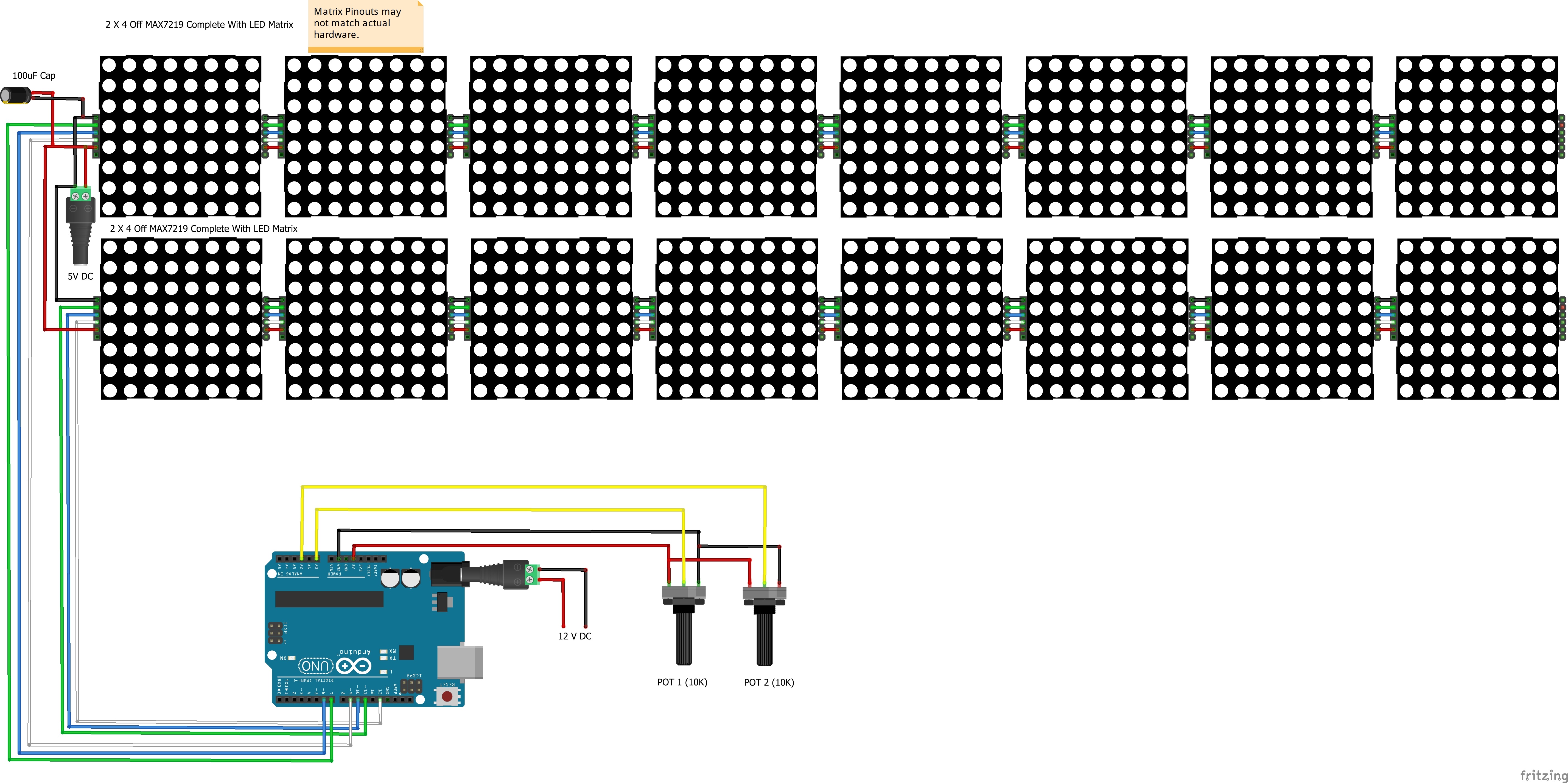
I am creating a sketch which takes the input from Three potentiometers and depending on the Value for each pot, drives a series of 16 8X8 MAX7219 LED Matrices for each Potentiometer, but having trouble getting this to operate as I expect.
To keep things simple initially I have set it up with one Potentiometer on Pin A0 and only 8 MAX7219 Matrices (FC16-HW) on Pot 1
My sketch does not seem to loop continuously and doesn't display the Columns of Leds dependant on the value of the input potentiometer (i,e, In the form of a Bar Graph)
I am probably missing the obvious but have studied the MD_MAX72xx library examples but just can't see where I am going wrong ??
Any pointers would be greatly appreciated, thanks.
Fimez.
// INCLUDES
// Used to control a panel of MAX7219 LED displays based on the input from a Potentiometer.
#include <MD_MAX72xx.h>
//#include <SPI.h>

// DEFINES
// Turn on/off debugging
#define DEBUG  1

#if  DEBUG
#define PRINT(s, x) { Serial.print(F(s)); Serial.print(x); }
#define PRINTS(x) Serial.print(F(x))
#define PRINTD(x) Serial.println(x, DEC)

#else
#define PRINT(s, x)
#define PRINTS(x)
#define PRINTD(x)

#endif
// Define the number of devices we have in the chain and the hardware interface
// NOTE: These pin numbers will probably not work with your hardware and may
// need to be adapted
#define HARDWARE_TYPE MD_MAX72XX::FC16_HW
#define MAX_DEVICES  8

#define CLK_PIN   13  // or SCK
#define DATA_PIN  11  // or MOSI
#define CS_PIN    10  // or SS

// SPI hardware interface
MD_MAX72XX mx = MD_MAX72XX(HARDWARE_TYPE, CS_PIN, MAX_DEVICES);
// Arbitrary pins
//MD_MAX72XX mx = MD_MAX72XX(HARDWARE_TYPE, DATA_PIN, CLK_PIN, CS_PIN, MAX_DEVICES);

// We always wait a bit between updates of the display
#define  DELAYTIME  100  // in milliseconds

// CONSTANTS
// The analogue input pins to which the potentiometers are connected.
const byte potPins[] = {A0, A1, A2};
// The total number of valves ****** Currently only one potentiometer in use ********
// Hopefully in the final sketch hope to use three Potentiometers a three lots of four 8X8 Matracies
const byte numPots = 1;

// GLOBALS
// This array will record the current reading of each input valve  **** Currently Only 1 In use *****
int currentReadings[numPots] = {};

/**
 * Initialisation
 */
void setup(){

    #ifdef DEBUG
    // Initialise serial communications channel with the PC
    Serial.begin(9600);
  #endif
  // Set the linear pot pins as input
  for(int i=0; i<numPots; i++){
    // Set the pin for the pot
    pinMode(potPins[i], INPUT);
  }

}

// Create a fixed map function:
long map2(long x, long in_min, long in_max, long out_min, long out_max) {
        return (x - in_min) * (out_max - out_min+1) / (in_max - in_min+1) + out_min;
}

/**
 *  Read the input from the potentiometer/s and store in the currentReadings array
 */
void getInput() {
  // Read the value from the pots
  for(int i=0; i<numPots; i++){
    // Get the "raw" input, which is a value from 0-1023
    int rawValue = analogRead(potPins[i]);
    int totalColumns = mx.getColumnCount();
    // Scale the value to the number of LEDs in each strip
    int scaledValue = map2(rawValue, 0, 1023, 0, totalColumns);
    // To ensure we don't get any dodgy values, constrain the output range too
    scaledValue = constrain(scaledValue, 0, totalColumns);
    // Store the scaled value in the currentReadings array
    currentReadings[i] = scaledValue;
    // Print some debug information
    #if DEBUG
      Serial.print("Valve ");
      Serial.print(i);
      Serial.print(" raw:");
      Serial.print(rawValue);
      Serial.print(", scaled:");
      Serial.println(scaledValue);
      Serial.print(", Total Colums  ");
      Serial.println(mx.getColumnCount());
      //delay(500);
    #endif
  }
}

/**
 * Set the LEDs dependant on the scaled value */
void setDisplay() {
  // Loop over each input
  for(int pot=0; pot<numPots; pot++)
  {
      //PRINTS("nCols 0->max");
      mx.clear();
      Serial.println("Display Should Be Clear");
      for (uint8_t col=(currentReadings[pot]); col<mx.getColumnCount(); col++)
      {
        mx.setColumn(col, 0x00);
        }
       for (uint8_t col=0; col<currentReadings[pot]; col++)
        {
        mx.setColumn(col, 0xff);
        delay(500);
            }
      }
}
 /**
 * Main program loop runs indefinitely
 */
void loop()
{
  getInput();
  setDisplay();

// Future Code To Be Written Once Sketch Completed To Operate
// With Three Potentiomenters and Three Strips of 4 8X8 Matracies
//
}