I have some MSGEQ7 bare IC chips. I have one on a breadboard working just fine with 7 LEDs to the 7 frequency bands doing PWM to audio headphone level input. Both left and right channel from the source are connected to the input pin of the chip, so there's no stereo distinction.
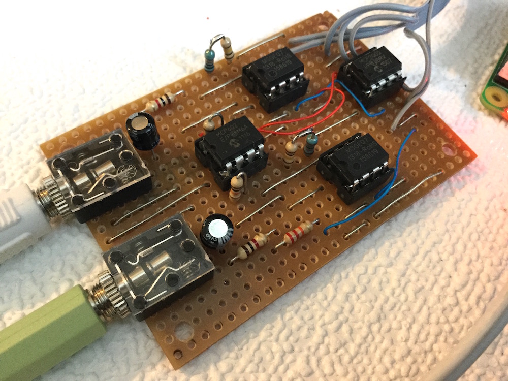
I'm planning on putting two of them on perf board for a semi permanent rig. One chip for each channel.
I'm wondering which components/aspects can be shared between the two chips.
For example, can they/should they both share the same Strobe and Reset pins from the Arduino, or do they each need their own?
Would they each need their own decoupling capacitors or can they just share one? Would the value of a shared one need to change when going to two chips?
I've never used the MSGEQ7 but I believe you can share the strobe & reset pins. (There is a timing diagram at the bottom of the datasheet.)
Would they each need their own decoupling capacitors or can they just share one? Would the value of a shared one need to change when going to two chips?
The general rule with digital and analog chips, is that every chip has a it's own bypass cap, mounted as close as possible to the chip's Vcc and ground pins And if the chip has more than one power-pin, each power-pin should have a capacitor. (Usually a PC board will work with a missing bypass cap or two, but if you want a reliable circuit follow the recommendations.)
Both left and right channel from the source are connected to the input pin of the chip, so there's no stereo distinction.
There is another general rule that you should never "short" outputs together.* If you want to do that, put a resistor in series with each output to make a passive mixer (1K or more would be fine with headphone outputs).
* If you short the left & right channels of a power amplifier, you'll probably fry it... You probably won't fry a headphone amp or a line-level output, but of course, you'll kill the stereo sound and you can get distorted sound or a situation where the 'center' information comes-through but the left-only & right-only signals are shorted-out.
Thanks for the info. I had thought that 3.5mm mono plugs just joined L and R but looking at it now, it only outputs the L/tip while the R/ring is grounded as sleeve. Good to know. Though I've mostly only had one channel plugged in for testing because it was less work that way.
The amplifier allows for a smaller audio input than an iPad at full blast. Note the way the virtual ground from each MSEQ is used for each side's amplifiers.
Note it was for a system without any built in A/D, you can miss that out and feed the analogue outputs directly into the Arduino.
I have noticed the rather insensitive MSGEQ7, level mismatch where the input has to be rather loud to fit nicely into the output display. I was considering using a pot to adjust values with coding (mathematically boosting the readings and just dealing with the smaller readings), but it might be under the realm of what the MSGEQ7 detects.
A gain pot is something I'm figuring out. Leave the passthrough level unaffected, just be able to adjust the output. But of course pots don't amplify, so I need to over-amp it a touch to give a usable range of attenuation. I'll have to look up those chips you used. I assume those are what's doing the signal amplification.
If it is DC it is not audio and the capacitave coupling removes any DC component anyway.
But - the input to the MSGEQ7 is a high impedance so you are after a voltage gain. Note that circuit I posted worked from a 3V3 supply. It is better from a 5V supply but you need more voltage on the input to get the outputs higher.
I found that without the amplifier the input volume had to be too high. Yes you could cut down the through audio signal with a pot but for balance it would have to be a two ganged pot. And you also run the risk of not having enough input voltage from your input source.
Didn't realize that the audio signal was actually AC. I thought it was analog DC.
That would explain some strangeness in connecting grounds when powering and audio sourcing from my PC at the same time.