I volunteer at a RR Museum in Bowling Green, KY that has a scale model railroad layout. The members want to add a thunderstorm scene. We have the sound and LED unit from BLI to provide that portion of things. It needs a dry contact closure for less than 2 seconds to initiate the sound and lightning effect. We want to trigger it with a motion sensor, but then limit it to not triggering again for 30 seconds. A FB group suggested Arduino Nano for the project and sent me info on how to hook up the motion sensor to the Nano, but in looking at the terminals of the Nano on the official site, I don't see an output point to provide the dry contact closure to initiate the thunderstorm. It appears there are just Digital and Analog input terminals. I already have a line on a motion sensor based on the responses in the FB post. Are there additional components I need beside the Nano? I sent the query to tech support and they sent me here.
The term 'dry contact closure' has no meaning here.
Almost any hobby Arduino will work, those pins are both input and output. VERY roughly and in a NON language what you need to do is
- Detect motion (1 input pin probably with INPUT_PULLUP)
- Various timers using the millis() technique documented in the tutorials here inder state or many things at once to implement the not retrigger for 30 secs, not sure what the 2 secs means, maybe raise the pin to HIGH for 2 secs?
Forum will design it for You. The best You can do is split the project into small parts and solve each small part. When You master them, put them together into one project, one code.
Links to datasheeta of not standard components are recommended.
-
A NANO will work for this.
-
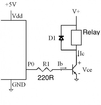
For the dry contact, an output on the NANO would connect to a base resistor connected to the base of a NPN BJT (2N2222).
5v to DPDT Relay coil, coil to NPN collector, emitter to GND.
place kickback diode across coil (example 1N4007).
Perhaps it's not internationally known but certainly in the UK a 'dry' contact is one independent of other circuitry. In practice that means a relay or switch contact not connected to anything else, or possibly an optical isolator output not connected to anything else.
@georonn , you are correct, there is nothing on a Nano capable of providing a dry contact output. Simplest would be a relay module, of which many are available from both your favourite e commerce site or hobby electronics site.
- In Canada, Dry is a simple contact (supplies no electron water stuff to a load).
Wet is a contact that switches a voltage, (supplies electron water to a load).
![]()
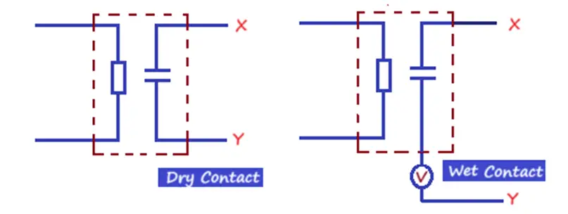
The circuit on the left will not cause that lightning and thunderstorm circuit to do anything; the one on the right will.
-
Actually it will work as the thunder circuit module that our dry contact is connected to detects the dry contact closure and proceeds to do its thing . . .
-
If the Arduino circuit wets the relay contact we call it a wet contact.
If the Load circuit wets the relay contact, we call the contact dry.
This one? 1632 Layout Lightning Storm
It advertises a "classic pushbutton" input, for which you would use a relay circuit, as mentioned by @LarryD
Ginger ale?

Nor is it Canadian any more.
Owned by Keurig Dr Pepper, an American company, since 2008.
Am I being punked?
- This is true:
* If the Arduino circuit wets the relay contact we call it a wet contact.
* If the Load circuit wets the relay contact, we call the contact dry.
- However what’s more important here is there is no Canada and no Ginger in my favourite Canada Dry !

![]()
I think you are saying exactly the same as me in a different way.
Please stick to the OP's topic.

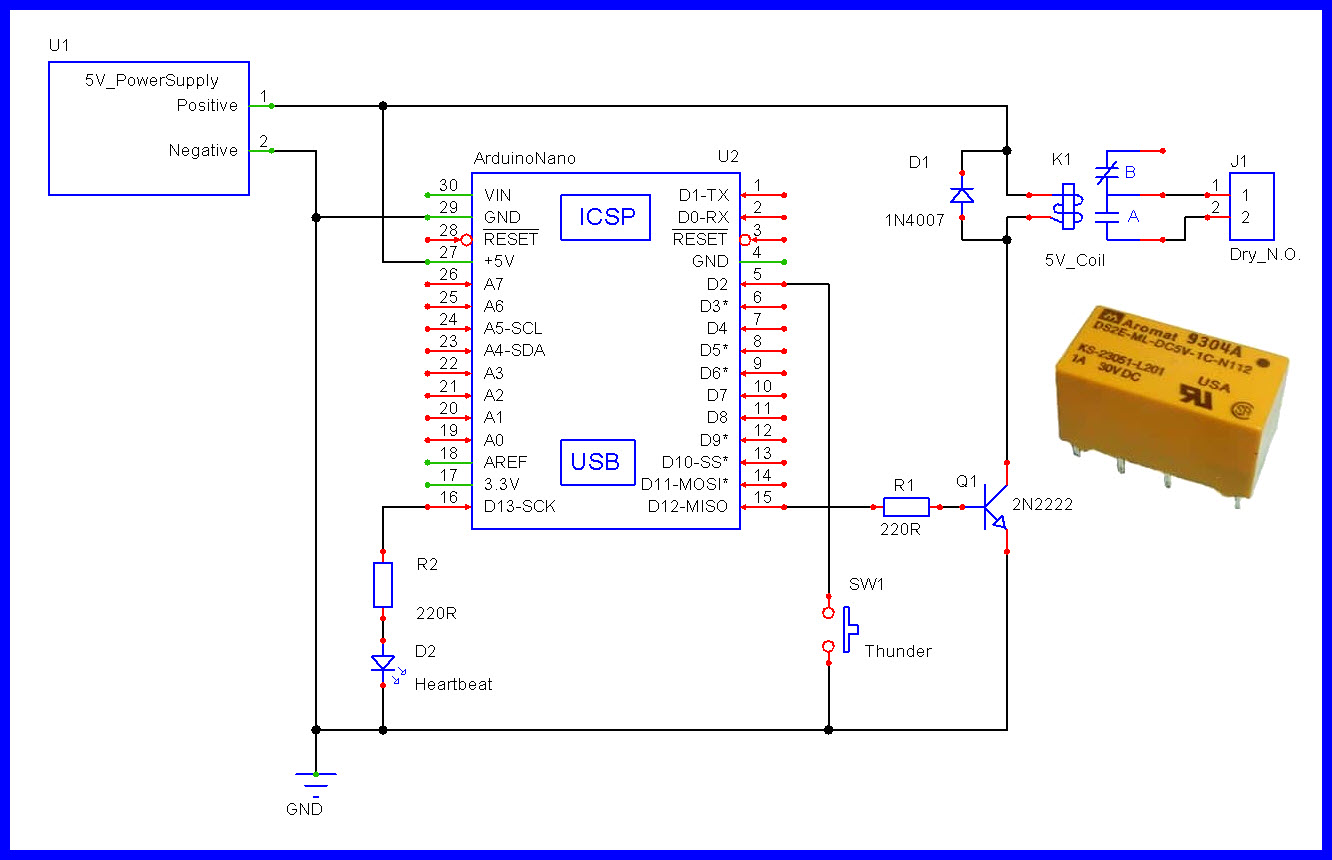
- This schematic and NANO C++ code should get you almost there.
//
//================================================^================================================
//                                  B a s i c   R a w   S k e t c h
//================================================^================================================
//
//  URL
//
//
//
//  Version    YY/MM/DD    Comments
//  =======    ========    ========================================================================
//  1.00       25/06/23    Running code
//
//
//
//
//  Notes:
//
//
//
//


//================================================
#define LEDon              HIGH   //PIN---[220R]---A[LED]K---GND
#define LEDoff             LOW

#define OPENED             HIGH
#define CLOSED             LOW

#define STOPPED            0
#define ENABLED            1
#define LOCKOUT            2

#define EXECUTEcode        true   //the code in the "State" is executed
#define BYPASScode         false  //the code in the "State" is not executed

#define RELAYon            HIGH   //a HIGH turns on the NPN transistor, the relay closes the dry contact
#define RELAYoff           LOW

//================================================
#define ONE_SECOND         1000ul              //milliseconds
#define ONE_MINUTE         (ONE_SECOND * 60ul) //60 seconds in one minute
#define ONE_HOUR           (ONE_MINUTE * 60ul) //60 minutes in one hour
#define ONE_DAY            (ONE_HOUR * 24ul)   //24 hours in one day


//                              G P I O s   A n d   V a r i a b l e s
//================================================^================================================
//

//Analogs
//================================================
//
const byte potentiometer          = A1;

//INPUTS
//================================================
//
const byte mySwitch1              = 2;

//OUTPUTS
//================================================
//
const byte relayCoil              = 12;
const byte heartbeatLED           = 13;

//VARIABLES
//================================================
//
byte lastMySwitch                 = OPENED;

unsigned long heartbeatTime;
unsigned long switchTime;

unsigned long relayOnTime;
unsigned long relayLockTime;
unsigned long relayOnInterval     = 2 * ONE_SECOND;      //2 second
unsigned long lockOutInterval     = 30 * ONE_SECOND;     //30seconds
byte relayTimerFlag               = STOPPED;


//                                           s e t u p ( )
//================================================^================================================
//
void setup()
{
  //Serial.begin(115200);

  digitalWrite(heartbeatLED, LEDoff);
  pinMode(heartbeatLED, OUTPUT);

  digitalWrite(relayCoil, RELAYoff);
  pinMode(relayCoil, OUTPUT);

  pinMode(mySwitch1, INPUT_PULLUP);

} //END of   setup()


//                                            l o o p ( )
//================================================^================================================
//
void loop()
{
  //========================================================================  T I M E R  heartbeatLED
  //Is it time to toggle the heartbeat LED ?
  if (millis() - heartbeatTime >= 500)
  {
    //Restart this TIMER
    heartbeatTime = millis();

    //toggle the heartbeat LED
    digitalWrite(heartbeatLED, digitalRead(heartbeatLED) == HIGH ? LOW : HIGH);
  }

  //========================================================================  T I M E R  switches
  //Is it time to check our switches ?
  if (millis() - switchTime >= 50)
  {
    //Restart this TIMER
    switchTime = millis();

    checkSwitches();
  }

  //========================================================================  T I M E R  relay On
  //If enabled, is it time to turn OFF the relay ?
  if (relayTimerFlag == ENABLED && millis() - relayOnTime >= relayOnInterval)
  {
    //Turn OFF the relay
    digitalWrite(relayCoil, RELAYoff);

    //Restart and enable TIMER lockout
    relayLockTime = millis();
    relayTimerFlag = LOCKOUT;
  }

  //========================================================================  T I M E R  relay lockout
  //If we are in lockout, is it time to allow normal relay operation again ?
  if (relayTimerFlag == LOCKOUT && millis() - relayLockTime >= lockOutInterval)
  {
    relayTimerFlag = STOPPED;
  }


  //================================================
  //       Other non blocking code goes here
  //================================================


} //END of   loop()


//                                   c h e c k S w i t c h e s ( )
//================================================^================================================
//
void checkSwitches()
{
  byte switchState = digitalRead(mySwitch1);

  //========================================================================  mySwitch1
  //Was there a change in state for this switch input ?
  if (lastMySwitch != switchState)
  {
    //Update to this new state.
    lastMySwitch = switchState;

    //========================
    //Is timing stopped and was this switch closed ?
    if (relayTimerFlag == STOPPED && switchState == CLOSED)
    {
      //Enable and Restart TIMER.
      relayTimerFlag = ENABLED;
      relayOnTime = millis();

      digitalWrite(relayCoil, RELAYon);
    }

  } //END of   mySwitch1

} //END of   checkSwitches()


//
//================================================^================================================
//
Thanks, Larry, I think this circuit and the operational code you've provided will get me going toward solving this issue for the museum. Much appreciated.
George