Yes, I often use jam nuts in similar situations.
In tight areas and with short threaded rods, the above mentioned process works well.
Yes, I often use jam nuts in similar situations.
In tight areas and with short threaded rods, the above mentioned process works well.
As with most here, I have collected pairs of pliers and wrenches over the years.
Every maker needs good tools and suggest you always buy the best.
I hate my crescent wrenches and my nonparallel pliers are the worst. 
Both always damage and round the corners of nuts and bolts.
On the other hand, a good set of ignition wrenches are a must in your lab.
Below is a discussion of what I consider the best alternative to the old timer tools.
If you have a few extra dollars (~$60.00), the Knipex Pliers Wrench will be your best tool (next to your oscilloscope  ).
These pliers are fantastic; the jaws are always parallel to each other, you can operate them with one hand and they do not mar your work.
The German made quality and steel is outstanding.
The 5” pliers go to 23mm (7/8”), the 7” pliers go to 40mm (1 1/2”).
Hey, if you are a plumber, there is a 10” version too.
You can make your solder wick more effective by following the procedure in images below.
A pair of flat jawed Knipex pliers does a great job of compressing the copper weave in solder wick.
We get a 10 to 1 lever action with the pliers, more than enough to flatten the wick.
Add a bit of liquid solder flux to the flattened wick. Also add about 2 mm of solder to the wick’s end.
Side Note:
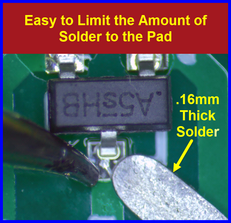
You can do similar to solder; the flattened solder makes it easier to limit the amount applied to PCB pads. See post #1015.
Flattening ‘silver solder’ is also a good way to limit solder to stainless steel.
Hi,
Also called "double walled adhesive heat shrink", the adhesive is quite robust under most conditions.
I use the pliers method on cable assembly that has two cables, 5mm diameter, in a sleeve, then they spread them at the end.
The double walled and clamping like that does the job.
What you will note with 4:1 is the more it shrinks, the thicker the wall becomes.
Tom... 


Or:
Further to post #1010.
Also see post :
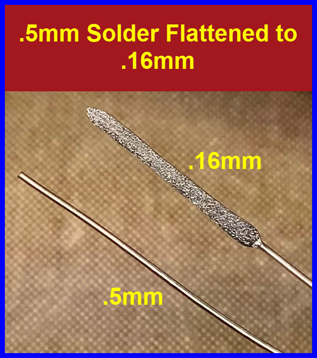
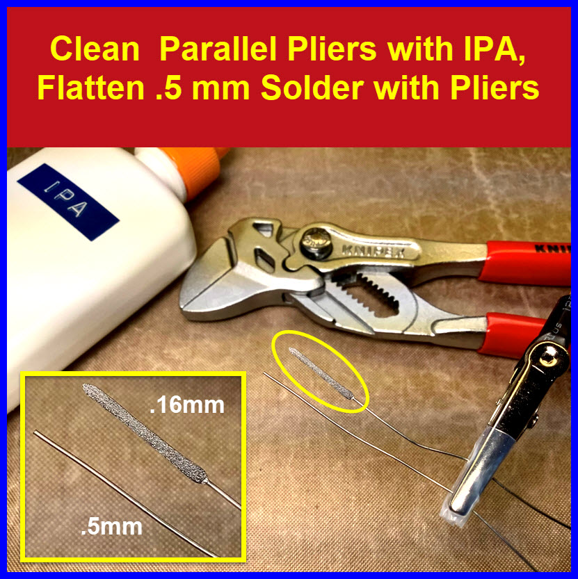
You can flatten solder to aid in hand soldering of small SMD components.
Use cleaned parallel pliers to flatten a length of .5 mm solder.
With the flattened solder, you have an easier job in limiting the amount of solder applied to your PCB pads.
You can find Terminal Tab Cold Insert Connectors for sale all over the internet.
These are made from brass and are quite reasonably priced, about 2 to 3 cents each in volume.
You can easily connect two wires as described in the images below.
The connection is strong and does not need soldering.
Note, using glue lined heat shrink makes your connection moisture proof.
If your connector can accommodate stacking the wire strands, follow the instructions given.
If your connector is small, you may not be able to stack the strands as shown.
FYI

In another post, a user asked how to terminate 28 AWG wire in a screw type terminal strip.
@6v6gt suggested to use a Dupont crimp connector to act as homemade ferrule.
Below shows how this process can be accomplished.
Add heat shrink to act as a strain relief.
The colour of this heat shrink can identify the terminal number to use:
Yellow would be terminal #4
Brown and Yellow would be #14, etc.
Great idea with the JST connectors, I'm glad my original question has inspired you 
I would also like to present some of my solutions for connecting tiny wires to terminal blocks;
This involves the use of crimp connectors; the type which are commonly used for automotive use. Specifically I am using blade connector's (DBN1.25-10) ( 5$ AUD for 200pcs on Aliexpress) and ring connectors (RV 1.25-4), as well as some good quality Irwin crimping pliers ( IRWIN VISE-GRIP Self-Adjusting Wire Stripper, 8",).
I believe the tiny ribbon cable I am using is around 26 gauge, but 28 gauge should work fine too.
First, I strip about 40mm of wire, twist it and then wrap it backwards over the insulation;
However, if the connector hole is big enough, I found it was even better to bend a bit of the insulation backwards over itself, and then wrap the twisted wire around it, like you can see below. This also improved the quality of the crimp, and meant I only had to crimp it once. You can compare the quality to my original post here; How to connect tiny signal wires into screw terminal blocks? - #10 by GigaNerdTheReckoning
I placed the connector inside before I wrapped the wire, which made it a lot easier to slide over the wire and insulation;
Then crimped like so;
These crimping methods are particularly useful for working with small gauge thermocouple wire, like we see below;
This also proves useful for many high amp Solid State Relays, which use large ring connector terminals on the low current input side to the relay;
Finally, here are the results for the blade connectors. Heat shrink is added for insulation and strain relief;
You can also bend one of the blade's slightly, to allow for multiple wires into a single pole of the terminal, but LarryD's solution seems better suited to this, as it provides more clearance.
If you have a 3D printer make shrouds to convert stray dupont pins into a real connector.
free download HERE
Page also has mounts for lots of Arduino modules.
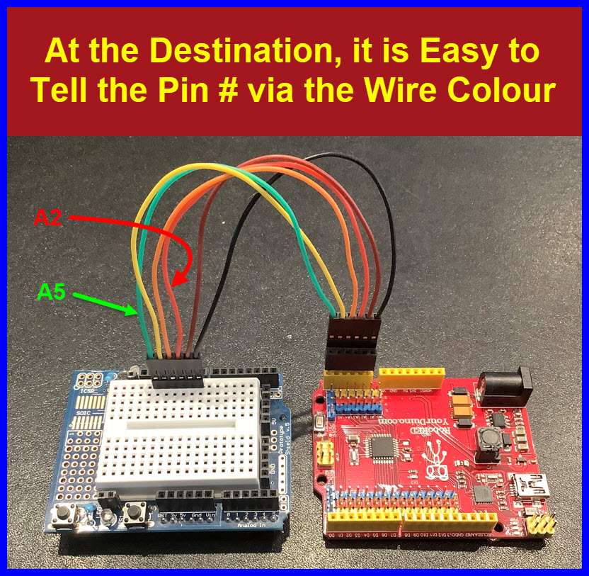
When you make up Dupont cabling, match the colour of the wire to the source pin it connects to.
Resistor colour code:
0    1  2  3  4   5   6  7   8  9
BK, BN, R, O, Y, GN, BE, V, SL, W
At the destination, it is easy to identify the source pin number.
When you come to pin 10 start again at Black . . .
Most of the time a ~10k pull down resistor is added from the Gate to the Source on MOSFETs.
This resistor prevents a floating Gate situation.
If you use SOT23 to SIP conversion PCBs, take advantage of the double-sided mounting of the board.
On one side solder your SOT23 MOSFET, on the other side solder a 0805 - 10k resistor between pins 1 and 2.
If your THD components have any height (like the capacitor or the LED in the examples above), add some extra structural strength by (hot) glueing them to the PCB after testing.
A SMD electrolytic capacitor has a small pedestal like addition to achieve this.
One accessory that every Arduino maker should have on their bench is a simple ammeter. Working with Arduino I've found the power distro native to the mega 2650 and UNO to be lacking. When the spec says 200mA total, it MEANS it. Powering the cards via USB causes the on board voltage to drop to 4.3V as the anti-backflow diode loses ~.7v. It doesn't take much to sop up 200 mA. In this project the scrolling LED's can draw up to 1A if all pixels are maximum brightness.
With this $15 analog 0-3A DC ammeter, you can see the current wax & wane as the display changes and the relay is energized. The peak current is around .6A, well beyond the .2A max for the Mega.
[
]Ammeter shows even at idle, draw is over 200mA limit.
The IR receivers have given me fits with them failing to trigger no matter what. FINALLY it was traced to a soft Vcc line. At 5.0V with 4A behind it the IR response is solid as a rock, as is all of the other functions.
- Electrical Characteristics
Absolute Maximum Ratings
DC Current VCC and GND Pins................................. 200.0mA
That's per VCC + GND pair. It looks like both pin packages for the ATmega2560 have four pairs making the absolute maximum 800 mA for the processor.
There are also per-port and per-pin limits.





 .