I have 2 APC220 radio module, one connected to an Arduino uno R3 that transmits data, and the other one connected to an Arduino nano that should receive the data. I see on my uno that transmission is working, but i do not receive anything. I also tried to use as receiving only the radio module connected to the pc, but i don't receive anything (I used cool term for serial reading). The configuration of the radio modules i did in the Arduino, they are both configurated the same. I can't see what is the problem.
Here is my Arduino Uno code (transmitter):
#include <SoftwareSerial.h>

SoftwareSerial mySerial(9,10);

int number = 0;

void setup() {

Serial.begin(9600);

mySerial.begin(9600);

}

void loop() {

(number ++);

Serial.print ("APC220 test ");

Serial.println (number);

mySerial.print ("APC220 test ");

mySerial.println (number);

delay (1000);

}
and here is my arduino nano code (receiver):
#include <SoftwareSerial.h>

SoftwareSerial mySerial(2,3);

void setup() {
  Serial.begin(9600);
  mySerial.begin(9600);
}

void loop() {
  if(mySerial.available() > 0){
    String input = mySerial.readString();
    Serial.println(input);
  }
  delay(20);
}
To troubleshoot the issue with your APC220 radio modules, here are some steps you can follow:
Check Connections
- Ensure Correct Wiring:
- Transmitter (Arduino Uno):
- APC220 TX to Arduino RX (pin 9 on Uno with SoftwareSerial)
- APC220 RX to Arduino TX (pin 10 on Uno with SoftwareSerial)
- GND to GND
- VCC to VCC (3.3V or 5V depending on your module specifications)
- Receiver (Arduino Nano):
- APC220 TX to Arduino RX (pin 2 on Nano with SoftwareSerial)
- APC220 RX to Arduino TX (pin 3 on Nano with SoftwareSerial)
- GND to GND
- VCC to VCC
Verify Configuration
- Module Configuration: Ensure both APC220 modules are configured correctly and identically. Parameters such as baud rate, channel, and address must match.
Test Each Component
- Testing Individual Components:
- Arduino to APC220: Verify that the Arduino can communicate with the APC220 module. For example, use
Serial.print and mySerial.print in a simple test to ensure data is being sent.
- APC220 Module to PC: Test each APC220 module with a PC using CoolTerm or another serial terminal to ensure they can send and receive data.
Code Improvements
- Improve Code: Make slight modifications to ensure robustness and include debug statements. Here's your modified code:
Transmitter Code (Arduino Uno):
cpp
#include <SoftwareSerial.h>

SoftwareSerial mySerial(9, 10);

int number = 0;

void setup() {
  Serial.begin(9600);
  mySerial.begin(9600);
}

void loop() {
  number++;
  String message = "APC220 test " + String(number);
  Serial.println(message);
  mySerial.println(message);
  delay(1000);
}
Receiver Code (Arduino Nano):
cpp
#include <SoftwareSerial.h>

SoftwareSerial mySerial(2, 3);

void setup() {
  Serial.begin(9600);
  mySerial.begin(9600);
}

void loop() {
  if (mySerial.available()) {
    String input = mySerial.readString();
    Serial.println(input);
  }
  delay(20);
}
Debugging Steps
- Debugging:
- Add print statements in both the transmitter and receiver code to verify that each step is executing as expected.
- Use an oscilloscope or logic analyzer to check the signals on the TX and RX lines of both modules.
Ensure Compatibility
- Check Compatibility: Confirm that both the Arduino Uno and Nano can operate with the voltage levels required by the APC220 modules. Some modules may require a 3.3V signal instead of 5V, and using the incorrect voltage can lead to communication failures.
Use Serial Monitor
- Serial Monitor: Open the Serial Monitor on both the transmitting and receiving Arduinos to verify the data being sent and received. Ensure that the baud rates in the Serial Monitor match the baud rate specified in your code.
Testing with Known Good Components
- Swap Components: Swap the APC220 modules to check if one of the modules might be faulty. You can also swap the Arduino boards to see if the issue is with the Arduino itself.
By following these steps, you should be able to isolate the issue and determine why the data is not being received.
Chat GPT it's not useful here. 
@lawliet666 chatGPT evidently doesn't know that use of String objects on Arduino often leads to program crashes, due to poor memory management, so avoid using chatGPT.
I did not know that. I also tried with sending just a number, but all I get is an "0".
I don't know if it is relevant, but i also verified if my arduino nano is listening, and it is.
There is nothing obviously wrong with your code, but you forgot to post a wiring diagram, and photo of the setup. Did you connect the grounds?
Instead of waiting for Strings, to get started, the receiver should just echo characters received, i.e.
#include <SoftwareSerial.h>

SoftwareSerial mySerial(2,3);

void setup() {
  Serial.begin(9600);
  mySerial.begin(9600);
}

void loop() {
  while (mySerial.available() > 0)   Serial.print(mySerial.read());
}
Make sure that the ACP220 modules are set for 9600 Baud.
i'm so sorry, but i don t know how to do a schematic, yet.
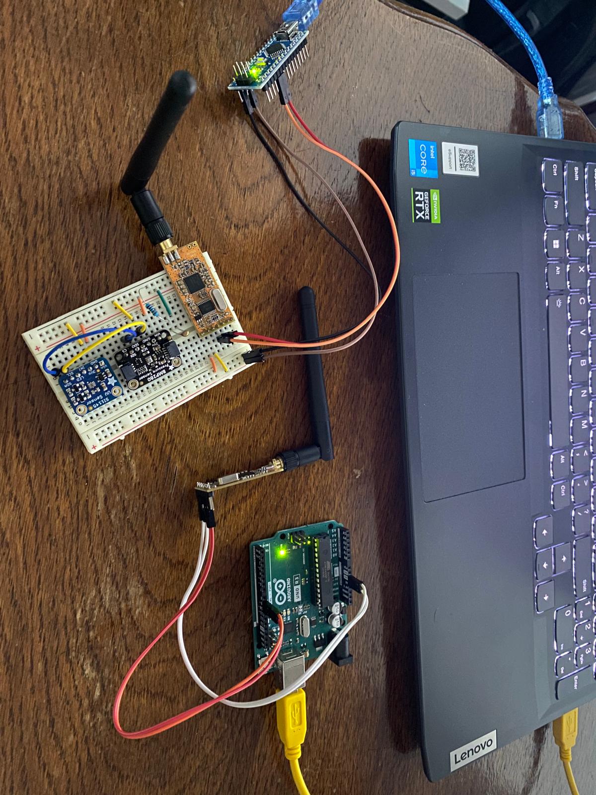
But i can tell you that the Rx, Tx from the module are connected to the pins specified in the code (rx - 9, tx - 10 and, rx - 2, tx - 3), gnd to gnd and vin to 5V. Here is an image with what I have.
It is the internationally accepted and understood language of circuitry, and very important.
After reading this brief tutorial, draw one with pencil and paper, using rectangles and lines, labeling each connection. Take a pic of it and post.
The photo is not useful as it does not clearly show the connections. Something like this, but clearly show power and ground connections.
Note: you need to connect TX on the module to the pin designated "RX" on the Arduino. Follow the instructions on the DFRobot site.
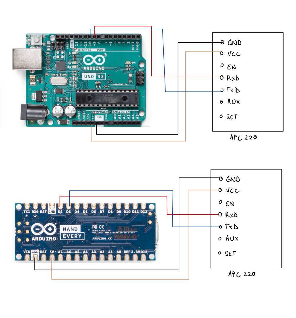
My schematic:
i modified in the code the pins, defined them:
#define rxPin 3
#define txPin 2
#define rxPin 10
#define txPin 9
and now it's receiving constantly, but i get the value "-1"
Never mind, It's working now. I had a problem with that delay(20), i put delay (1000), and with the modification of the pins as you said rx-tx, it now works. Thank you so much. 
PS: fortunately it works also with string
Great!
For a while, but eventually it will crash.