Using a Canon Printer Incremental Encoder + Datasheet

Hi.

While looking for myself, I found a lot of posts trying to reverse engineer the optical encoders found in Canon printers.
https://forum.arduino.cc/t/how-to-make-an-incremental-optical-encoder-with-2-phases-cheaply/889652
https://forum.arduino.cc/t/reading-printer-optical-encoder/319027

Well, I found the datasheet!

I noticed, at least in the generation I'm finding in bins, they tend to use Kodenshi units.

The catalogue entry:

If the old posts were still open I would have linked to the data sheets there.

Typical Characteristics:


The 2 digit number stamped on the back of the unit seems to indicate the resolution in Lines Per Inch (LPI):
Capture5

Data sheets were available here:
https://www.kodenshi.co.jp/top/en/products/sensor/encoder/
https://www.kodenshi.co.jp/top/wp-content/uploads/2020/10/KE-2△10F-□.pdf

https://www.kodenshi.co.jp/top/wp-content/uploads/2020/10/KE-2△13F_□-new.pdf
https://www.kodenshi.co.jp/top/wp-content/uploads/2020/10/KE-2△19F-□-new.pdf

Pictures of the ones I have. They look to be 150 and 360 LPI units:


Well, I successfully read the worm drive encoder.

I counted the notches on the wheel by placing white paper behind the disc and taking a high resolution photo with my SLR, which was placed as a background in a CAD package. I counted 40 notches and measured the included angle, which suggested there were around 440 notches on the disc.

To confirm, I made an array of lines around the centre of the disc and looked for moire patterns. I found that there is actually has 441 notches on this disc. It also revealed that the disc isn't printed perfectly, and the notches are a slightly different pitch in one section. Maximum deviation is about 1/3rd of a notch over about 150 notches. I was careful to ensure correct alignment, the centre of the image circle and a high quality Olympus OM lens to minimise and at least even out lens distortion.

1 Like

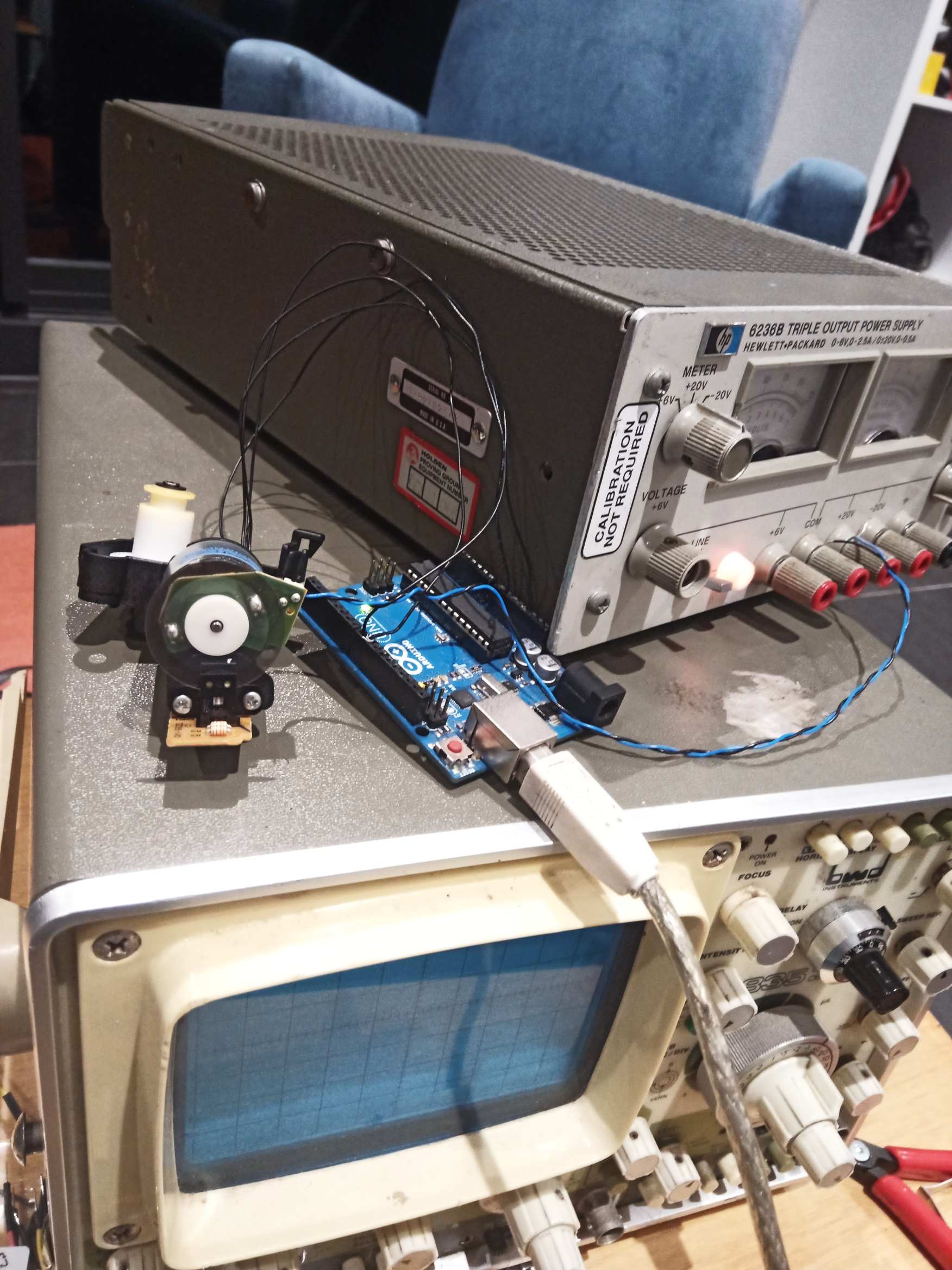
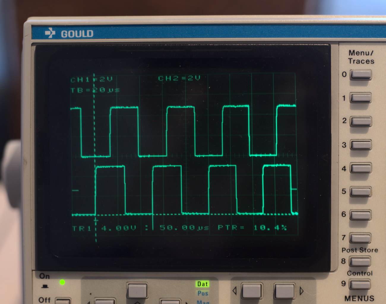
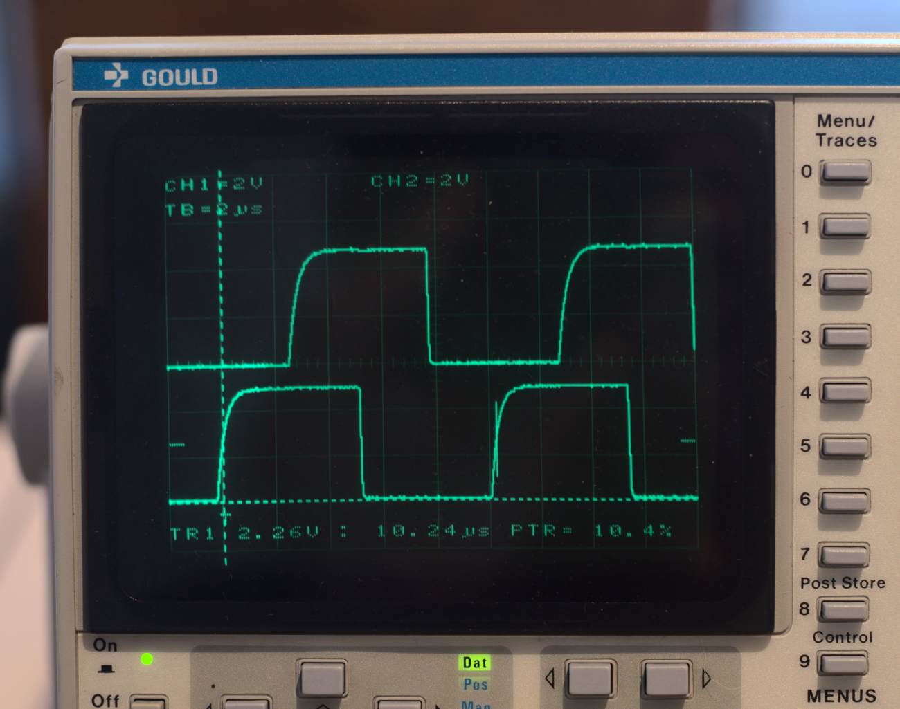
I then wrote up a sketch to read the encoder. It is implemented on a UNO and uses direct access to port registers to speed up the interrupt handler. A pin change interrupt is used to trigger on each edge of both of encoder waveforms, giving a resolution of 4 x the slot count (1/1764 of a rotation). The sensor gives a nice clean wave with its inbuilt hysteresis circuit, so noise and 'bounce' are not a concern.

This sketch just sends raw position count. Shaft angle and RPM will be added later.

/* *******************************
   ** WOOTER'S MOTOR CONTROLLER **
   **                           **
   *******************************
*/

#include <avr/interrupt.h>
#include <Arduino.h>
#include <stdint.h>
#include <stdbool.h>

volatile uint8_t OldState = 0;
volatile int32_t Position = 0;
volatile bool InvalidInc  = 0;
const int8_t IncArray[4][4]= {0,-1,1,2,1,0,2,-1,-1,2,0,1,2,1,-1,0};

void setup() {
  Serial.begin(19200);
  pinMode(8, INPUT);
  pinMode(9, INPUT);
  PCICR  |= 0b00000001;      // "PCIE0" PORT B pin change interrupt enabled
  PCMSK0 |= 0b00000011;      // Mask for "PCINT0 & PCINT1" pins set enabled -> D8-D9 will trigger interrupt
}

void loop() {
  delay(100);
  Serial.println(Position,DEC);
  if (InvalidInc) {
      Serial.println("LOST COUNT");
      InvalidInc = 0;
  }
}

ISR (PCINT0_vect) {
  uint8_t State = PINB & 0b00000011;
   int8_t Inc = IncArray[OldState][State];
   OldState = State;
   Position += Inc;
   InvalidInc |= (Inc == 2);
}

The idea of using the lookup array is taken from here:
https://cdn.sparkfun.com/datasheets/Robotics/How%20to%20use%20a%20quadrature%20encoder.pdf

Using a pin change interrupt on both pins essentially implements the XOR shown.

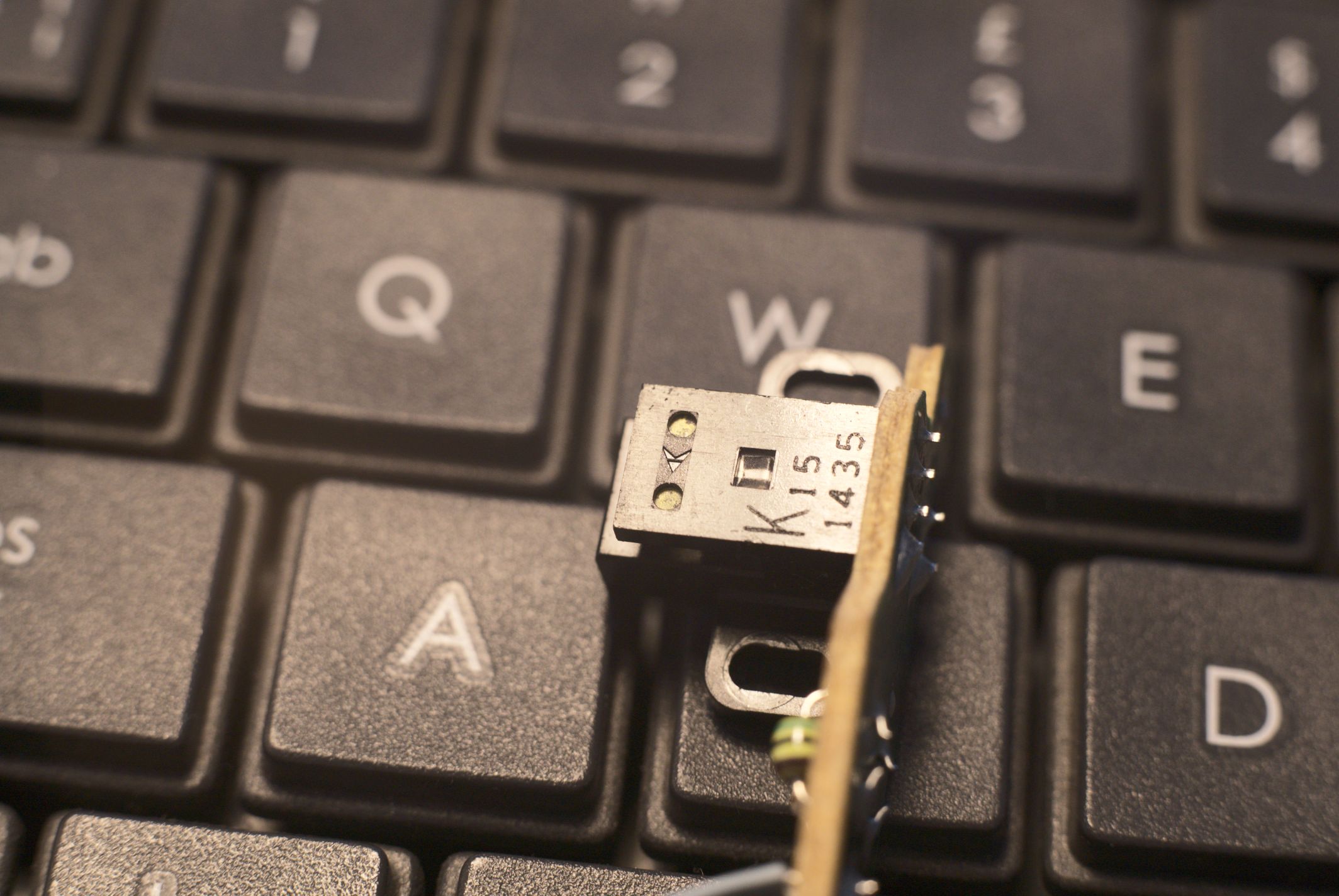
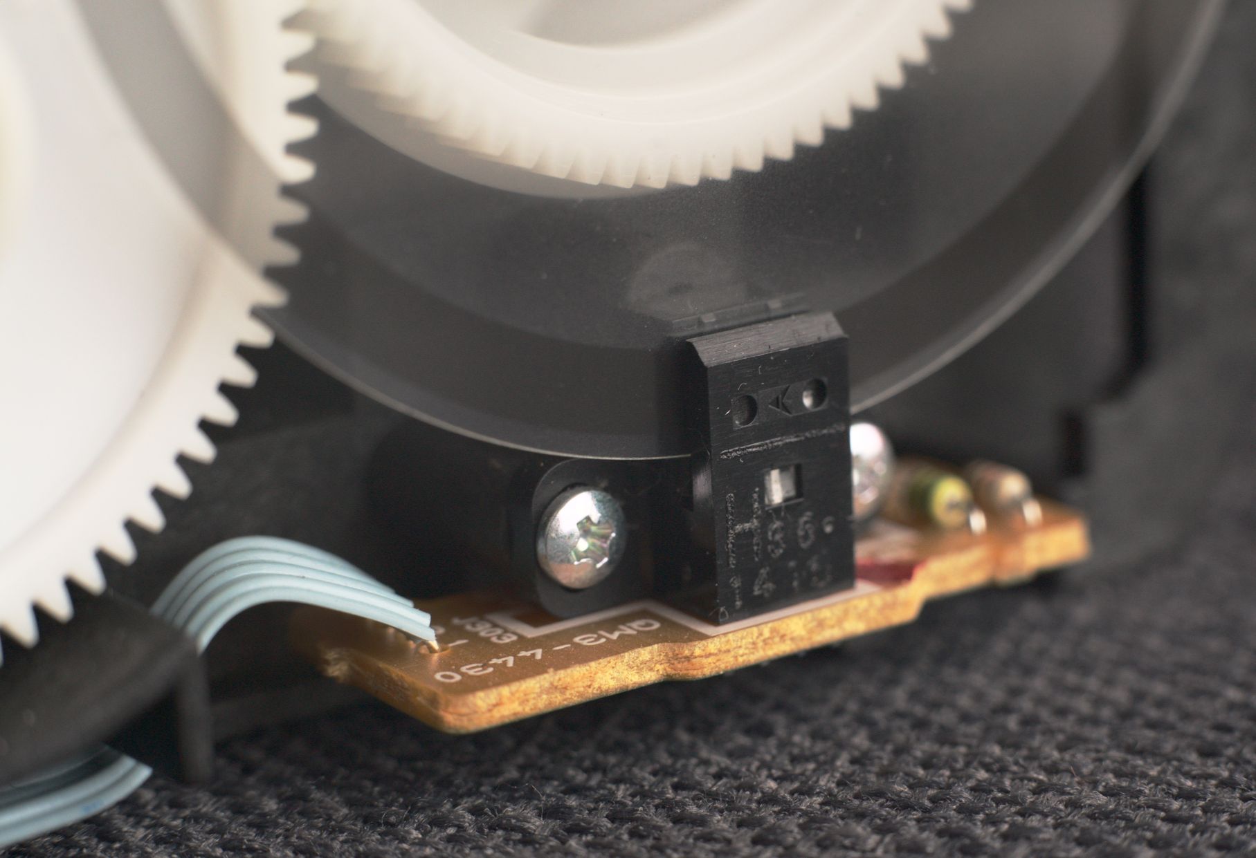
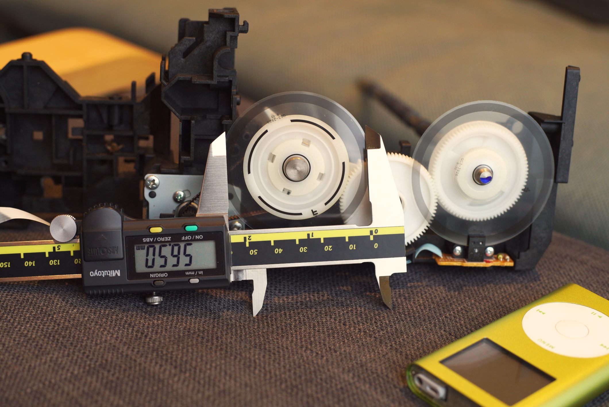
Confirming my numbers where correct, I made a small mark on the disk and read the count after 1 rotation, 40 rotations and some time running on the power supply. Each time the position counter aligned very closely with the number of rotations which indicates the system maintains its position count well

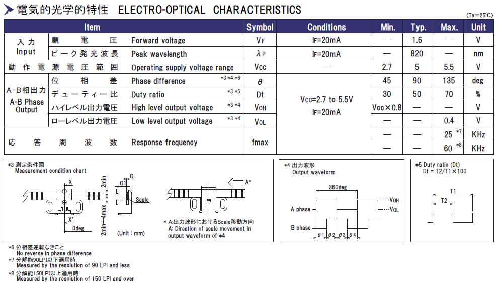
I should add that I used the datasheet above to trace the function of the wires. The small PCB already has the current limiting resistor for the LED, so using the 1.6v forward voltage, 20mA drive current and a measurement of the resistor (82ohm) I determined the board was designed to take 3.3V. Which, is available on the UNO. Handy!

The following code relays shaft RPM and interrupt frequency via serial.

The UNO is surprisingly fast. The system doesn't begin to miss counts until it is running at around 2,850 RPM which equates to an interrupt frequency of around 85kHz. This limit is the arduino, that begins missing edges of the signal. The oscilloscope shows good signal edges at this speed. As we are triggering on both edges of both signals, the frequency quoted on the datasheet is not the same as the interrupt frequency. It is in fact 1/4 of the interrupt frequency (1 cycle = 2 edges, 1 cycle * 2 signals = 4 edges). At the maximum speed the arduino can handle, the sensor is running at 85/4, 21kHz which is well below the maximum 60kHz quoted on the data sheet.

/* *******************************
   ** WOOTER'S MOTOR CONTROLLER **
   **                           **
   *******************************
*/

#include <avr/interrupt.h>
#include <Arduino.h>
#include <stdint.h>
#include <stdbool.h>

#define WHEEL_SLOTS 441
#define CLOCK_FREQ 16000000
#define TIMER_PRESCALE 256

volatile uint8_t OldState = 0;
volatile int32_t Position = 0;
volatile bool InvalidInc  = 0;
const int8_t IncArray[4][4]= {0,-1,1,2,1,0,2,-1,-1,2,0,1,2,1,-1,0};
int32_t PrevPosition = 0;

volatile uint8_t Timer2Rollover = 0;

void setup() {
  Serial.begin(19200);
  pinMode(8, INPUT);
  pinMode(9, INPUT);
  PCICR  |= 0b00000001;      //Bit2 = 1 -> "PCIE0" enabeled (PCINT0 to PCINT7)
  PCMSK0 |= 0b00000011;      //Bit5 = 1 -> "PCINT0 & PCINT1" enabeled -> D8-D9 will trigger interrupt

  TCCR2A  = 0b00000000;     //Reset entire TCCR2A register
  TCCR2B  = 0b00000110;     //Set TCCR2B register for 256x Prescaler
  TIMSK2  = 0b00000001;
  TCNT2   = 0;
}

void loop() {
  
  delay(10);
  
  int32_t PositionCopy = Position;
  uint16_t TimeVal = TCNT2 + 255*Timer2Rollover;
  TCNT2   = 0;
  Timer2Rollover = 0;
  
  int16_t DeltaPosition = PositionCopy - PrevPosition;
  PrevPosition = PositionCopy;
  float Frequency = float(DeltaPosition) * CLOCK_FREQ / float(TimeVal) / TIMER_PRESCALE;
  float RPM = Frequency / WHEEL_SLOTS / 4 * 60;

  Serial.print("Sensor Frequency: ");
  Serial.print(Frequency,DEC);
  Serial.print(" RPM: ");
  Serial.println(RPM,DEC);
  
  if (InvalidInc) {
    Serial.println("LOST COUNT");
    InvalidInc = 0;
  }
  
}

ISR (PCINT0_vect) {
  uint8_t State = PINB & 0b00000011;
   int8_t Inc = IncArray[OldState][State];
   OldState = State;
   Position += Inc;
   InvalidInc |= (Inc == 2);
}

ISR(TIMER2_OVF_vect){
  Timer2Rollover++;                       // Increment overflow counter
}

Another quick observation. The Pitch Circle Diameter, the diameter where the slot pitch is truly the specified 150 Lines Per Inch, appears to be in the middle of the slot width. As you would probably expect.

For this wheel, I've back calculated the diameter from my previous measurements
441 lines / 150 LPI / π * 25.4 = 23.77 mm

So, to estimate the number of slots in an unknown disc, I would start by measuring the PCD at the middle of the slot and calculate the number of slots using the LPI specification printed on the encoder.

The larger ones I got out of the same printer seem to be 360 LPI discs with 2,500 line resolutions :open_mouth:

Given the ~80 kHz limit of the arduino, the fastest you could spin these would be around 510 RPM

If you trigger on the falling edge of A and read B, you would need only 1/4 the interrupts and potentially get get 4x the RPM at 1/4 the resolution.

I thought I should post some scope shots of the output waveform.

Nothing special is done to the wiring. Resistors were sized to run the sensor off 5V as described above

441tooth @ 500RPM. 272.1μs/tooth, 3.7kHz sensor frequency, 14.7kHz interrupt frequency

Max Arduino speed
441tooth @ 2721RPM. 50.0μs/tooth, 20.0kHz sensor frequency, 80.0kHz interrupt frequency

Specified Max Sensor speed
441tooth @ 8163RPM. 16.7μs/tooth, 60.0kHz sensor frequency, 240.0kHz interrupt frequency

Max Motor Speed achieved on my power supply (around 22V)
441tooth @ 13287RPM. 10.24μs/tooth, 97.7kHz sensor frequency, 390.6kHz interrupt frequency

I like how codancrux re-wrote the code to be more readable. Cheers mate

Keeping this thread open because I have nearly finished designing an incremental decoder out of 74 series logic capable of much higher speeds

1 Like

This topic was automatically closed 180 days after the last reply. New replies are no longer allowed.