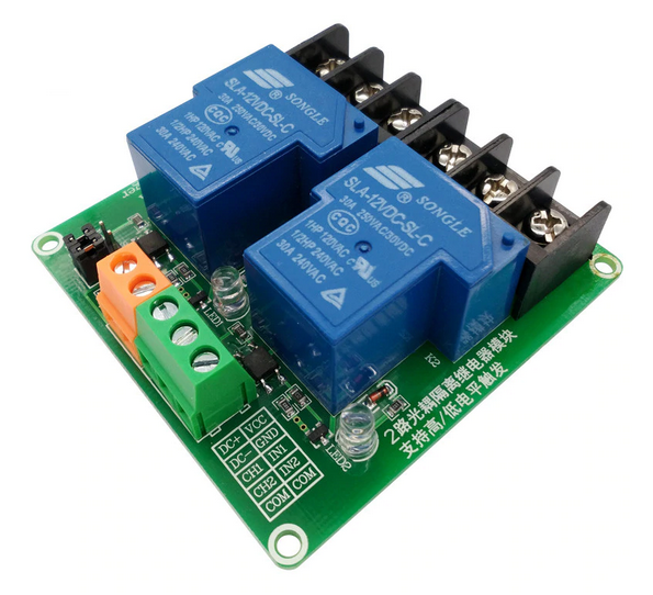
I don't see a jd-vcc input on this thing. I don't understand how this would work? It seems the optocoupler and the relay coil are powered by the same source. The product description states "SMD optocoupler isolation, strong driving ability, stable performance; trigger current 5mA."
Also, the product description states, "Maximum load: AC 250V/10A, DC30V/10A." But the relay doesn't seem to say anything about 12VD in the picture.
ryangrg:
I don't see a jd-vcc input on this thing. I don't understand how this would work? It seems the optocoupler and the relay coil are powered by the same source.
As shown, yes. However (similar to the "JD-VCC" modules) by removing the jumpers and connecting your input return to the middle pin, you can effect isolation. The optocouplers are dual LED types to allow for the polarity switching.
ryangrg:
The product description states "SMD optocoupler isolation, strong driving ability, stable performance; trigger current 5mA."
Yes, I suppose it does.
ryangrg:
Also, the product description states, "Maximum load: AC 250V/10A, DC30V/10A." But the relay doesn't seem to say anything about 12VD in the picture.
Indeed it doesn't, but generally these relays are indeed rated at 30 V, 10 A. As the "10A 250VAC" is duplicated I suspect it is a cheap clone. The datasheet cites 10 A at 28 VDC.
I thought the jumper that's in the picture is for switching between HIGH/LOW triggering. I was thinking that rather than remove the jumper completely, you move them between high and low positions. Would one then plug external power to the exposed pins, labeled as S1 and S2? Here's another angle:
I believe the schematic for your relay module is very similar to this where only one relay circuit is shown. In order to achieve opto-isolation (galvanic isolation), there can't be a common ground crossing the yellow line. Therefore the relay module needs to have its own DC supply that's isolated from the Arduino supply. From the diagram, you can see that you'll need to connect as Paul__B describes.
It's crazy that most of these low cost relay modules have opto isolators, but the design to configure them that way is an afterthought rather than default. In your case, you'll need to remove both jumpers. You can still use high or low level trigger depending on if you connect the middle pin to Arduino GND or Arduino 5V.
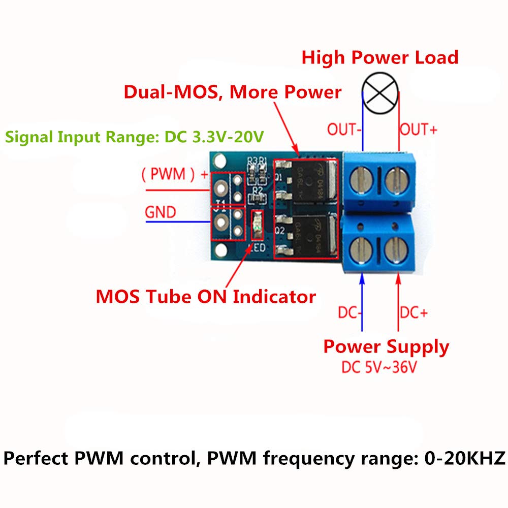
Controlling DC is difficult for a relay ... the contacts are prone to welding closed and getting increased wear. Make sure your DC load has adequate protection against flyback voltage by using a diode (at least 10A with high reverse voltage rating). Using a MOSFET would be a better fit, but if you need to use relays, this module would be a much better choice (same configuration as above). Datasheet Note that the NO contact has the better rating (20A/30VDC), whereas the NC contact is only 10A/30VDC. Therefore, using COM and NO contacts would be rated at 20A/30VDC.
@dllyod Thank you for the information! By the looks of the connectors alone the relay you provided a picture of seems much better. I am using a 2 channel relay to control a 12V actuator that has a spiking current of 9 amps and will have sustained current through operation of 5.5 amps under the target load. Probably the max rate the relay will be triggered is about once every 20 or 30 seconds, but I need it to be very reliable. When you talk about flyback voltage would that be to the relay power supply or to the actuator in my case? Also, in the relay module you posted a link to is the flyback voltage protection built in?
I've been trying to figure out the right questions to ask on here for my application? I think I'm almost there and should probably post something more direct in the project guidance forum. Right now I have the relay I posted a picture of in route, but I don't think I plan on using it in my final design.
When you talk about flyback voltage would that be to the relay power supply or to the actuator in my case?
Here, I mean clamping the spike from the solenoid to 12V. Looks like you'll need at least a 10A+ diode with a high reverse voltage rating.
Probably the max rate the relay will be triggered is about once every 20 or 30 seconds, but I need it to be very reliable.
There will be significant operations over time, controlling a heavy DC load. Really, a suitable MOSFET board is the best way to achieve a highly reliable switching circuit. I would suggest looking for an opto isolated MOSFET board.
It's crazy that most of these low cost relay modules have opto isolators, but the design to configure them that way is an afterthought rather than default.
I think I understand what you mean here, why have a relay with an opto isolator when you can just use the opto isolator? I assumed opto isolators couldn't handle the heavy load. That and I've been piecing together my circuit design for the actuator control from the progressive automations instructable pages.
I don't think I need the PWM control though. I just need the motor to go or not, that and I'd like to control 16 actuators from one MEGA, and it looks like there are only 12 PWM io's on the MEGA and I'll need 32 channels for total control of all the actuators.
Correct, you wouldn't need or use PWM, just digital outputs. No opto isolation but that shouldn't be a problem because the MOSFETs will switch the load cleanly. Just need at least 10A diodes with high reverse voltage rating installed across the actuators, diode cathode connected to +12V.
If you are reversing current to the actuator to reverse direction, you cannot use 1 diode, it would be a short circuit in 1 direction. You COULD use a full wave bridge rectifier wired correctly across the actuator. I would use an H-bridge motor controller with at least 15 Amp current rating.
@jca34f Won't a full wave bridge rectifier wired across the actuator just cause the motor to always turn in one direction? I thought it's application is to convert AC to DC. Also, I was checking out motor controllers, I thought they would be overkill but some are pretty cheap. Was checking out something like this Cytron. Is it normal for motor controls to have a shared ground between the io and motor? Is this something to be concerned about?
@dlloyd If I'm doing an H-bridge with the relays I'm confused by what you mean by:
clamping the spike from the solenoid to 12V
Do you mean placing a diode in the relay trigger circuit? Or does this involve some kind of full wave bridge rectifier wired across the actuator? Also if I used a relay that had 12V trigger could I share that with my motor power supply without an issue - is this were a diode would be important?
To give a little more detail on the duty cycle. The critical operation period would be for a few months, maybe a year, running around three or five hours a day with the actuators only needing to be triggered at a max rate of once every 30 seconds, this max rate wouldn't always be happening. Then set-up may go into hibernation before being used again, on the same schedule.
@dlloyd If I'm doing an H-bridge with the relays I'm confused by what you mean by:
Whoa ... H-bridge? So the solenoids are single coil activated and non self-returning, so they need reverse voltage applied to return? I guess it would be really good to see a schematic and part#s at this point.
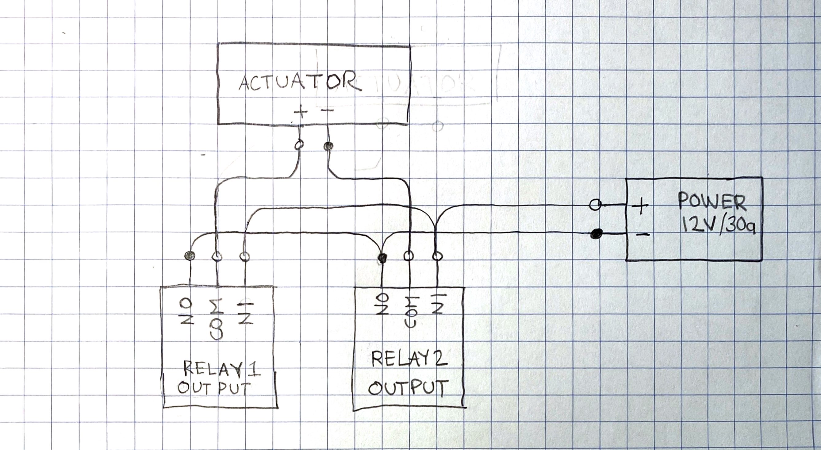
Yes, a full-wave bridge with its "~" terminals connected to the actuator and "+" and "-" to positive and negative supply terminals would nicely provide "kickback" protection to the relay contacts, just as it would in an H-bridge which almost always incorporates this in the design.
@Paul__B When I say "between" I mean the COM outputs from my relays going the actuator. So in the diagram I provided the actuator terminals connect to the ~ terminals of the full wave bridge and COM outputs, which represent the supply, are connected to the + and - ends of the bridge? I'm not able to make this work when I model it and it doesn't make sense to me how it would allow the circuit to flow in both directions which must happen to allow CW and CCW rotation of the DC motor. Are you able to show me a diagram of what you mean?
An MOV is a bidirectional TVS. However, it has a much higher joule rating and much higher peak current rating. If you use TVS, make sure that its bi-directional type.