Arduino nano ATmega328PB upload issue

I bought 3 Arduino nano clones from Aliexpress and have been having problem with uploading. Strangely I was initially able to upload a blink sketch but not anymore. After searching online and on the forum I found that the issue is the chip 328PB used on these clones, which is different from the 328P. And possibly the bootloader (old vs new?).
I found several videos and post but none of them works.
This is what I have done so far:
1-added a minicore board which I understand supports the PB version
2-used an arduino uno as an ISP to flash the new bootloader on the nano.

still not able to upload

I am not sure if I completed step 2 properly, this is what I get from the verbose:

Avrdude version 8.0-arduino.1
Copyright see https://github.com/avrdudes/avrdude/blob/main/AUTHORS

System wide configuration file is C:\Users\inhk\AppData\Local\Arduino15\packages\MiniCore\tools\avrdude\8.0-arduino.1\etc\avrdude.conf

Using port            : COM4
Using programmer      : stk500v1
Setting baud rate     : 19200
AVR part              : ATmega328PB
Programming modes     : SPM, ISP, HVPP, debugWIRE
Programmer type       : STK500
Description           : Atmel STK500 v1
HW Version            : 2
FW Version            : 1.18
Topcard               : Unknown
Vtarget               : 0.0 V
Varef                 : 0.0 V
Oscillator            : Off
SCK period            : 0.0 us
XTAL frequency        : 7.372800 MHz

AVR device initialized and ready to accept instructions
Device signature = 1E 95 16 (ATmega328PB)
Erased chip

Processing -U lock:w:0xff:m
Reading 1 byte for lock from input file 0xff
in 1 section [0, 0]
Writing 1 byte (0xFF) to lock, 1 byte written, 1 verified

Processing -U efuse:w:0b11110101:m
Reading 1 byte for efuse from input file 0b11110101
in 1 section [0, 0]
Writing 1 byte (0xF5) to efuse, 1 byte written, 1 verified

Processing -U hfuse:w:0xd7:m
Reading 1 byte for hfuse from input file 0xd7
in 1 section [0, 0]
Writing 1 byte (0xD7) to hfuse, 1 byte written"C:\Users\inhk\AppData\Local\Arduino15\packages\MiniCore\tools\avrdude\8.0-arduino.1/bin/avrdude" "-CC:\Users\inhk\AppData\Local\Arduino15\packages\MiniCore\tools\avrdude\8.0-arduino.1/etc/avrdude.conf" -v -patmega328pb -cstk500v1 -PCOM4 -b19200 "-Uflash:w:C:\Users\inhk\AppData\Local\Arduino15\packages\MiniCore\hardware\avr\3.0.4/bootloaders/urboot/atmega328pb/watchdog_1_s/autobaud/uart0_rxd0_txd1/led+b5/urboot_atmega328pb_pr_ee_ce.hex:i" -Ulock:w:0xff:m
, 1 verified

Processing -U lfuse:w:0b11111111:m
Reading 1 byte for lfuse from input file 0b11111111
in 1 section [0, 0]
Writing 1 byte (0xFF) to lfuse, 1 byte written, 1 verified

Avrdude done.  Thank you.
Avrdude version 8.0-arduino.1
Copyright see https://github.com/avrdudes/avrdude/blob/main/AUTHORS

System wide configuration file is C:\Users\inhk\AppData\Local\Arduino15\packages\MiniCore\tools\avrdude\8.0-arduino.1\etc\avrdude.conf

Using port            : COM4
Using programmer      : stk500v1
Setting baud rate     : 19200
AVR part              : ATmega328PB
Programming modes     : SPM, ISP, HVPP, debugWIRE
Programmer type       : STK500
Description           : Atmel STK500 v1
HW Version            : 2
FW Version            : 1.18
Topcard               : Unknown
Vtarget               : 0.0 V
Varef                 : 0.0 V
Oscillator            : Off
SCK period            : 0.0 us
XTAL frequency        : 7.372800 MHz

AVR device initialized and ready to accept instructions
Device signature = 1E 95 16 (ATmega328PB)
Auto-erasing chip as flash memory needs programming (-U flash:w:...)
specify the -D option to disable this feature
Erased chip

Processing -U flash:w:C:\Users\inhk\AppData\Local\Arduino15\packages\MiniCore\hardware\avr\3.0.4/bootloaders/urboot/atmega328pb/watchdog_1_s/autobaud/uart0_rxd0_txd1/led+b5/urboot_atmega328pb_pr_ee_ce.hex:i
Reading 384 bytes for flash from input file urboot_atmega328pb_pr_ee_ce.hex
in 1 section [0x7e80, 0x7fff]: 3 pages and 0 pad bytes
Writing 384 bytes to flash
Writing | ################################################## | 100% 0.41s
Reading | ################################################## | 100% 0.23s
384 bytes of flash verified

Processing -U lock:w:0xff:m
Reading 1 byte for lock from input file 0xff
in 1 section [0, 0]
Writing 1 byte (0xFF) to lock, 1 byte written, 1 verified

Avrdude done.  Thank you.

I am not very familiar with burning bootloaders and also I am not clear what setting should I used - once I have successfully done that - to upload a skecth on the nano.

from the verbose it looks like the bootloader process run smoothly but if I connect the nano I still cannot upload and also when I press reset on the nano there are no signs of blinking on the on board leds, the only sign is that the tx led is no longer constantly on (as it was before flashing the bootloader), only the Pwr led is on. apart from this no much luck in getting any code on the board.

What I posted earlier might help.

@camsysca
Thanks a lot. I had missed your post when searching!

this was the key issue:

Note - I already have the CH340 USB driver loaded, as I use it all the time for my Nano clones.

I installed the driver (instruction and download link here: [How to Install CH340 Drivers - SparkFun Learn]

then I was able to upload using the MiniCore board with settings shown in the picture

it's working now (finger crossed....)

but note that it only worked on the nano in which I had previously flashed a bootloader using an arduino uno. So this appears to be necessary, when I try to upload directly on a new board, it would not work.

finger crossing didn't help... strangely enough after successfully uploading a sketch on a nano I repeated the process for my other two boards and it didn't work. So either I have done something different the first time without realizing or this things are just temperamental....
the driver is now installed, I have flashed the bootloader via arduino on them but it won't upload even using the same exact settings. funny enough it wont even upload on the nano on which I previously uploaded a sketch successfully...

now I just get this:

Avrdude version 8.0-arduino.1
Copyright see https://github.com/avrdudes/avrdude/blob/main/AUTHORS

System wide configuration file is C:\Users\inhk\AppData\Local\Arduino15\packages\MiniCore\tools\avrdude\8.0-arduino.1\etc\avrdude.conf

Using port            : COM9
Using programmer      : urclock
Setting baud rate     : 115200
Error: cannot open port \\.\COM9: Access is denied.


Error: unable to open port COM9 for programmer urclock

Avrdude done.  Thank you.
Failed uploading: uploading error: exit status 1

it appears that the board is connected and the debug message (from the sketch I uploaded on it previously) is printing regularly on the serial monitor, but the IDE cannot upload a new sketch on it (and the debug message keeps on printing)

Which bootloader did you flash? The AVR Optiboot one or the Minicore urclock one?

Was it you who left a message just a minute ago? the message has been removed...
I follow that advise (closing serial monitor, removing the board, restarting IDE, then replugging the board) and it worked, but 1) did not understand what I did wrong in the first place and 2) I had to repeat the process to do it again and does not always work...

@ BitSeeker when I flashed the bootloader I selected MiniCore Board. so presumably the minicore one

UPDATE:
it looks like I can upload a sketch if disconnect and reconnect the board and if I am fast enough to press upload before the sketch on the board is running. Once the sketch is running it won't work anymore

Guilty as charged. I did start with that, but then figured I'd check what boot-loader it is first. If you had the AVR library selected and burned the Optiboot boot-loader, then tried to upload using the Minicore library which expects the urclock boot-loader, then that would not have worked, so I wanted to check that first. If you uploaded the Minicore one, then that's not the issue. Your board selection and options look good for a 328PB as well. I take it it definitely has a 16MHz crystal?

Its not unknown sometimes that if the port being accessed by another process when an upload request is made, that the board gets reset, but Windows sees the port as being busy and assigns another COM port to it, but the IDE displays the original port which is no longer accessible because the board has moved to another port in the background.

There is also a known bug in relation to the Serial Monitor, especially if its open in another window, although I have not experienced this myself:

I am not sure whether this might have been fixed in more recent versions of the IDE or whether it still surfaces occasionally.

Usually, if one shuts down serial monitor, the IDE and unplugs the board, that should clear any processes that might be hogging the serial port and one can start over.

That does not explain the behavior described in your last comment though. Can I ask what sketch you uploaded? It wasn't a keyboard/HID by any chance was it?

It's just a simple sketch that prints out the word "working" on the serial monitor every second. :slight_smile:
in the meantime I found this [MiniCore uploading problems] and a further chatgpt enquiry gave me this response:

That behavior confirms that the bootloader is only active briefly after power-up, and your sketch is likely interfering with future uploads once it's running.

What's happening:
On reset (or reconnect), the bootloader runs first, waiting for a short time (e.g. 500 ms–2 s) for a new upload.

If no upload begins, it runs the sketch.

Once the sketch is running, serial upload can fail if:

The sketch uses the serial port (blocking upload),

The auto-reset mechanism (via DTR) isn’t reliably triggering a reset, or

The reset pin isn’t cleanly returning to bootloader mode (e.g. if the board entered the spurious HVPP state, as discussed earlier).

Why the reconnect-then-upload trick works:
When you reconnect the board, it resets and powers up cleanly. If you press “Upload” during the short bootloader window, it catches the request and works. But once your sketch is running (and especially if it uses Serial), that window is gone.

How to fix this long-term (without changing your programmer):
Add a diode from RESET to VCC (1N4148, anode to RESET, cathode to VCC) to prevent the false HVPP trigger. This stabilizes reset behavior and allows reliable uploads even after the sketch starts.

Ensure your sketch doesn't immediately block Serial. ie while (!Serial);

Check your auto-reset circuit.

If your board lacks the usual DTR → 0.1 µF → RESET cap setup, AVRDude may not be able to reset it.

Or, if you have it but no clamp diode, the cap might trigger spurious behavior (as discussed).

Optional: Use “Upload Using Programmer” to bypass the bootloader entirely (if you’re using ICSP), but this is slower and overwrites the bootloader unless you flash it back later.

so the question is if it is a hardware problem... which nanos with a 328PB chip have?

That is an interesting bit of information. I was not aware of the diode mod. There seems to be a variety of these Nano clones around. A lot of them now seem to have the USB-C connector although its still possible to get ones with a Micro-USB port. I ordered a Nano recently and it has the 328PB onboard and the USB-C connector. Allegedly it also has the FTDI UART chip, although the markings were removed and the chip has the same package as the CH340..... I have not experienced any problem using the urclock boot-loader with this one, but have actually just ordered a couple more with the CH340 onboard to compare.

Its not a problem with the 328PB chip as such, but does sound like a problem with the way the UART is implemented on the board.

As per the last line, its useful to have a USBASP programmer to hand. They are quite cheap and will allow you to work around the serial problem and reset a blocked board. Or else you can use a spare Arduino board as an ICSP programmer.

Thanks for this advice. I think I will buy one of these... read that it will erase the bootloader, which is not a big deal if you use the USBASP to program the board all the time. I suppose it also uses the space reserved for the bootloader ? (Hence gaining space?)
Until I get that I will probably just stick to reset the board by disconnecting and reconnecting before uploading.

If you get the new nano and find to have the same issue please let me know how you got to resolve it

A lot of them now seem to have the USB-C connector

yes, that's the one I have got

Those are fixed. There is another one that is still outstanding:

From my experience, it only occurs when using boards that have the FTDI FT232R USB to serial chip. I have not experienced it when using boards that have the CH340 (which it seems is the chip on @fluxia's board). However, it is definitely worth checking.

@fluxia, please try uploading normally after closing Serial Monitor/Serial Plotter:

Serial Monitor

  1. Click the X icon on the "Serial Monitor" tab in the bottom panel of the Arduino IDE window to close the tab:
  2. Upload the sketch.
  3. Open Serial Monitor again if needed (by clicking the icon on the IDE toolbar or the Tools > Serial Monitor menu item) after the upload is finished.

Serial Plotter

If you have the "Serial Plotter" window open, the procedure is a bit different from closing the Serial Monitor connection:

  1. Close the "Serial Plotter" window.
  2. If the "Serial Monitor" view is not already open, select Tools > Serial Monitor from the Arduino IDE menus to open it.
    We must do an open/close cycle on Serial Monitor as a workaround for a bug in Serial Plotter
  3. Click the X icon on the "Serial Monitor" tab in the bottom panel of the Arduino IDE window to close the tab:
  4. Upload the sketch.
  5. Open Serial Monitor and/or Serial Plotter again if needed after the upload is finished.

@ptillisch
thank you but this doesn't work.
I have plugged in the nano via a switched USB HUB to avoid taking it out and it from the usb. Switching the nano off and on just before uploading is the only thing that consistently work, so it must be a issue with the board reset(?)... All the three nano boards I bought act in the same way.

But note that pressing reset on the board itself does not help with the sketch uploading. the reset button works fine. it resets the board. maybe it's a timing issue.... at this point the short term solution is clearly to press the usb hub switch just before uploading and it will work, but it would be nice to understand what is causing this issue and how to resolve it.

It resets the ATmega328PB, but it doesn't affect the CH340 chip on the board (notice that the serial port of the board remains visible on your computer even if you hold down the reset button). When you power cycle the board, it causes the port to disappear and then reappear on your computer. It seems like you then have a time window to perform an upload before whatever other process grabs control of the serial port once more.


Microsoft provides a free tool named Process Explorer that can be used to identify the process that is using the port and causing the upload error.

  1. Click the following link to open the documentation page for Process Explorer in your web browser:
    https://learn.microsoft.com/sysinternals/downloads/process-explorer
  2. Click the "Download Process Explorer" link on that page.
  3. Wait for the download to finish.
  4. Extract the downloaded file.
  5. Double click on the file named procexp.exe in the extracted folder.
    The Process Explorer application will start.
  6. Select Find > Find Handle or DLL..." from the Process Explorer menus.
    "Process Explorer Search" dialog will open.
  7. Type \Device\Serial in the "Handle or DLL substring:" field of the dialog.
  8. Click the "Search" button.
    A search will start, as indicated by the presence of the text "Searching..." at the bottom of the dialog.
  9. Wait for the search to finish.

You should now see a process listed in the search results. Hopefully the name of the process will give you enough of a clue to identify the application that is blocking the serial port. If so, either close the port in the application, or else close the application, then try uploading again. Hopefully the upload will be successful this time.

If you aren't able to identify the application from the process name, add a reply here on this forum topic to let us know, including the name of the process.

thanks for the detailed advice. Unfortunately, the search finds no application (I made the search with arduino IDE running and serial monitor active and also wafter closing the monitor):

Just to be sure, does your board have a CH340 USB chip?:

📷

SparkFun - CC BY-SA 4.0 (cropped)

I know you already mentioned that you installed the CH340 driver, but sometimes people install that driver even though their board doesn't have a CH340 just because there is so much advice on the Internet about solving upload problems by installing that driver.


the chip is not marked, this is a picture

Most often when we see these strange unlabeled chips, they do identify themself as a CH340. However, there are some more rare cases where the chip identifies itself as an FTDI FT232R:

  1. Connect the board to your computer with a USB cable.
  2. Open the Windows Device Manager.
  3. Select View > Devices by type from the Device Manager menus.
  4. Open the "View" menu.
  5. If there is a to the left of the "Show hidden devices" menu item, click on "Show hidden devices" to disable it.
  6. Open the "Ports (COM & LPT)" section of the Device Manager tree.
  7. Find the port of the board under the "Ports (COM & LPT)" section. Double click on that item.
    A dialog will open.
  8. Select the "Details" tab in the dialog.
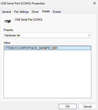
  9. Select "Hardware Ids" from the "Property" menu.

If it is identifying itself as a CH340, then we would expect to see something like this in the "Value" field of the dialog:

USB\VID_1A86&PID_7523&REV_0254
USB\VID_1A86&PID_7523

However, if it is one of the chips that identifies as FT232R, then it would instead be something like this:

FTDIBUS\COMPORT&VID_0403&PID_6001

Bingo!!


Thank you very much!!!

I am looking into how to get it working now.

OK, this is bad news because, unlike the dodgy unlabeled "CH340", we haven't managed to find techniques for making the boards with these chips work normally. In addition to the EEV Blog forum discussion I linked in my previous reply, there are a few others about these chips here on Arduino Forum:

Maybe you could find something of interest there.


But circling back to the "Process Explorer" results, it makes sense that you didn't get any processes because the form of the FT232R's "handle" is different from that of the CH340, so the CH340-specific search query I provided in my previous instructions is inappropriate for the FT232R. You can try it again with these adjusted instructions:

  1. Double click on the file named procexp.exe in the extracted folder.
    The Process Explorer application will start.
  2. Select Find > Find Handle or DLL..." from the Process Explorer menus.
    "Process Explorer Search" dialog will open.
  3. Type \Device\VCP in the "Handle or DLL substring:" field of the dialog.
  4. Click the "Search" button.
    A search will start, as indicated by the presence of the text "Searching..." at the bottom of the dialog.
  5. Wait for the search to finish.

(note that this time the search query is "\Device\VCP" instead of "\Device\Serial")

thanks for the links!

I was actually looking at this one, but haven't tried it yet

now I get a result when searching:

this also shows the drivers on my COM3 port, I am not sure if I need to uninstall them... I will check these links and see if there is a way to get it sorted but I am not very optimistic at this point. Fortunately I still have the option of uploading with manual reset ....