I was wondering if anyone might be able to take a look at this and tell me what I might be doing wrong. I believe I am within the realm of necessary voltage and resistance, as I successfully hooked up a single TPIC6B595 on a breadboard with resistors and necessary voltage, and was able to control one of these large segments just fine. Now that I have scaled it out and daisy chained registers, I can't seem to control them.
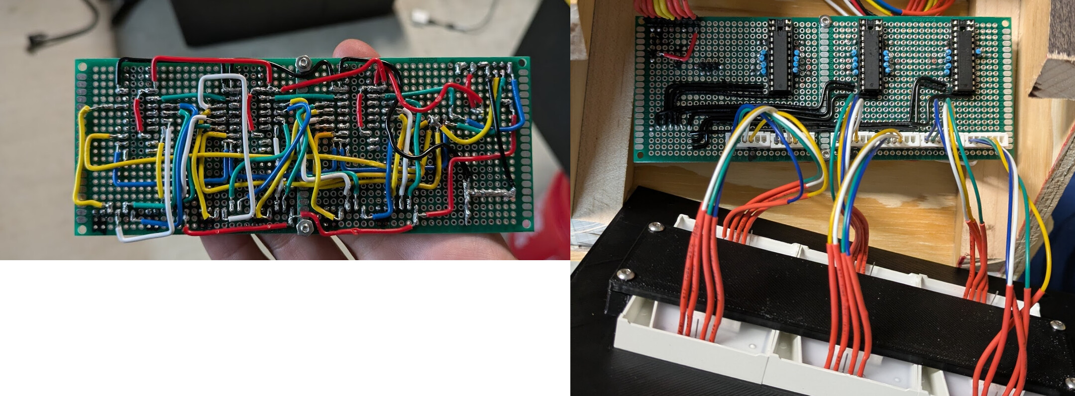
I have hand wired this whole portion of the project (its not pretty), so I fear I may have crossed some streams somewhere, resulting in its uncontrolled behavior; however, I wanted to post here as a sanity check to make sure my diagram on paper seems logical.
The hand wiring of this was pretty brutal, and I think I may look into having a custom PCB printed to reduce the possibility of error in my wiring. If anyone has any suggestions on a easy to use/learn PCB design software, that would also be awesome. I will be doing some research on that soon.
Only a moment. I see resistors in the pictures, looked because I missed them in your circuit drawing.
The wiring looks very good for the method you have chosen.
I woukd try removed the two distal shift registers and see if one display unit works like it did on the breadboard. You can put one shift register in only, try each slot by jumping the serial signal over the missing shift register(s) for the other two when they are tested solo.
I don't see any capacitors near your ICs, it is essential to place a 0.1 uF ceramic cap across the power lines as close as possible to each IC.
Lastly, remove all chips and disconnect eveything, get out your ohmmeter or continuity checker and confirm the wiring. I use a highlighter to draw over a large copy of the schematic.
Test until you may find shorts between signals, or missing/wrong connections.
It should be fine driving the 5V supply of the from the Arduino 5V pin:
[Edit, 777 hadn't posted when I started writing the above, I didn't see 777's post until after I posted my reply]
Thank you all for your time and informed suggestions. It does seem to be the general consensus that I have forgotten the 0.1uf capacitors near the registers. I have a bag of 100nf caps here and will give that a try here next.
Given that my current wiring of these registers looks like this:
Where would the best place to put these capacitors at? I understand they need to be close to the VCC of the chip, and connected to ground. Would something like this be feasible?
This is a good point that I had not considered. I think I was mentally assuming all ground connections can merge and are created equal, but I did not consider passing in/out of the arduino and/or ground looping it.
My drawing is a little misleading, as I have the arduino side of this on a breadboard currently. Here is what it actually looks like, so I may have inadvertently grounded it correctly without thinking about it lol.
Because the power and ground to the TPIC6B595 are on opposite pins then the very best way is to use a surface mount capacitor. You can do this by cutting a thin piece of track between the holes with a scalpel or hobby knife, and bridging the gap with a surface mount capacitor. Like this:-
Or in the OP's case an SMD capacitor on the bottom side soldered to the Vcc pin, the other end to a PCB pad then use a wire to the GND pin next door (maybe .1" away) .
That does seem like the ideal solution with the SMD cap; I think if/when I end up having a PCB created, I would go that route. I only had the classic caps in my bag of parts, so I gave that a try last night; unfortunately no luck.
Basically all of the lights stay on, so at first glance it does not appear that any communication is happening with the registers. I need to do some single register testing, and probably breaking out the multimeter to do some tracing.
I did also notice the ams1117 regulator on the bottom of the nano gets quite warm. It got to about 45c after a few minutes, but did seem to stabilize there. Granted I am feeding it 12v, which is its maximum, and it wont hit a thermal throttle until 150c, but it still seemed quite warm. The PCB around it was getting into the mid 50s as well. I think I may just need to add a heatsink, or another buck converter to feed the VIN less, and just send the 12v directly to the LED panel.
Thank you all again for the input, it has been very helpful.
It wouldn't hurt either to take a magnifier (10X at least) and a bright light and inspect all the connections. There may be a cold joint or bridge between two points that shouldn't be connected.
Use a 1206 100nF SMD resistor as Mike mentioned in his post above.
Use IPA (Isopropyl Alcohol) to clean of the flux residue from the soldering.
If it gets in the sockets, clean the sockets very well with the same IPA until you are sure no flux remains.
Edit: I guess I've never powered a Nano from 12V, but it's hard to see what the Nano would be doing to make the regulator heat up. You have the power LED and you're sending out the data via SPI, but nothing else. Can you measure the current flowing into the Nano from the buck regulator?
Edit2: Well, 40mA with a 7V drop would be about 300mW. I guess that would heat up the regulator some.
These boards look very useful. I often find myself with a PCB order which could easily carry a few more boards with little additional marginal cost so I may design something similar to this example but with a few additional features such as mounting holes and maybe some partial cuts so it could also be uses as half size for a smaller project. I'd then use such a design to bulk out a PCB order.
Yes, I find it easier for my one-of projects to use one of these instead of designing a board and waiting for it. They are not made of FR4 material, but seem to hold up pretty well. Edit: you need to steel wool the copper though to get it ready to solder.
Designing your own version would be pretty cool, but I've wondered if the board houses might balk at having to drill all those holes. The copper is simple, but the holes would take some time. There might be a surcharge.